
Modular fuel conditioning system

a fuel conditioning system and module technology, applied in the field of module fuel conditioning systems, can solve the problems of affecting the quality of the fuel that can be used with the turbine, the manufacturer's warranty of a large natural gas fuel-powered turbine is typically voided, and the fuel provided from the pipeline supplying the turbine with fuel does not meet the requirements,

Inactive Publication Date: 2005-06-07
PIPELINE CONTROLS
View PDF11 Cites 138 Cited by
  • Summary
  • Abstract
  • Description
  • Claims
  • Application Information

AI Technical Summary

Benefits of technology

The system provides comprehensive fuel conditioning, continuously adapting to changing conditions, ensuring optimal turbine operation, safety, and emissions performance while providing verification data for warranty purposes, thereby preventing damage and ensuring compliance with manufacturer requirements.

Problems solved by technology

In the field of natural gas fuel powered turbines, the manufacturers of the turbines put very strict restrictions upon the quality of the fuel that can be used with their turbines.
In some countries the fuel, provided from a pipeline supplying the turbine with fuel, does not comply with these restrictions.
The manufacturer's warranty for a large natural gas fuel-powered turbine is typically voided, if fuel is used that does not meet the manufacturer's fuel requirements.
Therefore, not only should the pressure be limited to a restricted range of values, but the maximum rate of change in pressure should also be limited.
None of these prior systems is believed to consistently meet all of the criteria set by turbine manufacturers.

Method used


Image

  • Modular fuel conditioning system
  • Modular fuel conditioning system
  • Modular fuel conditioning system

Examples


Embodiment Construction

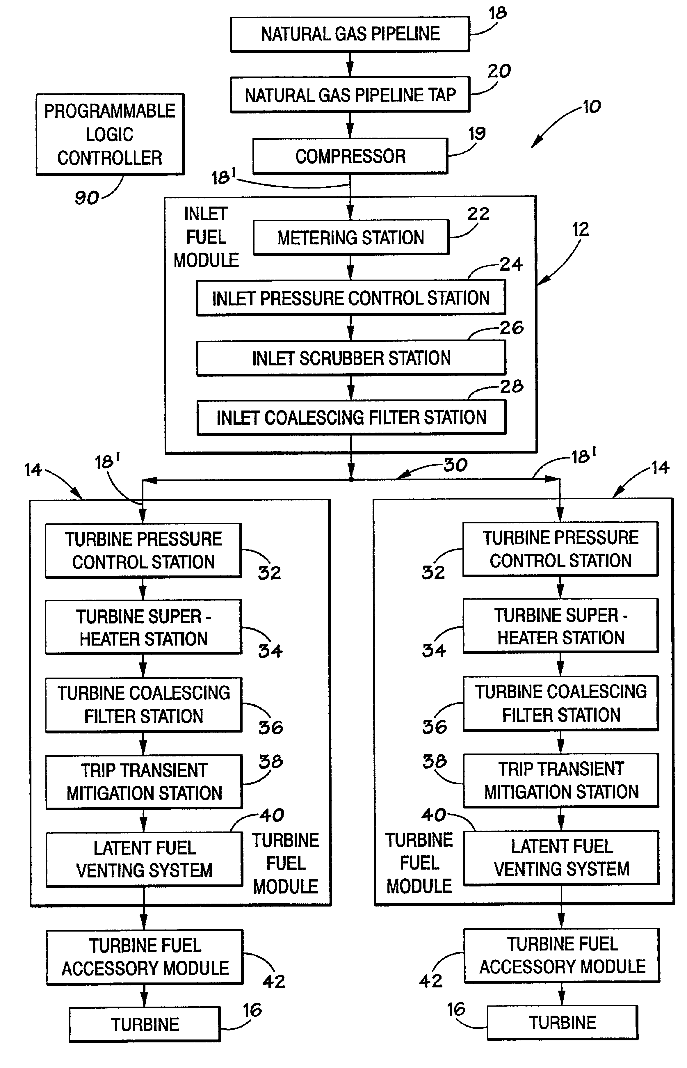
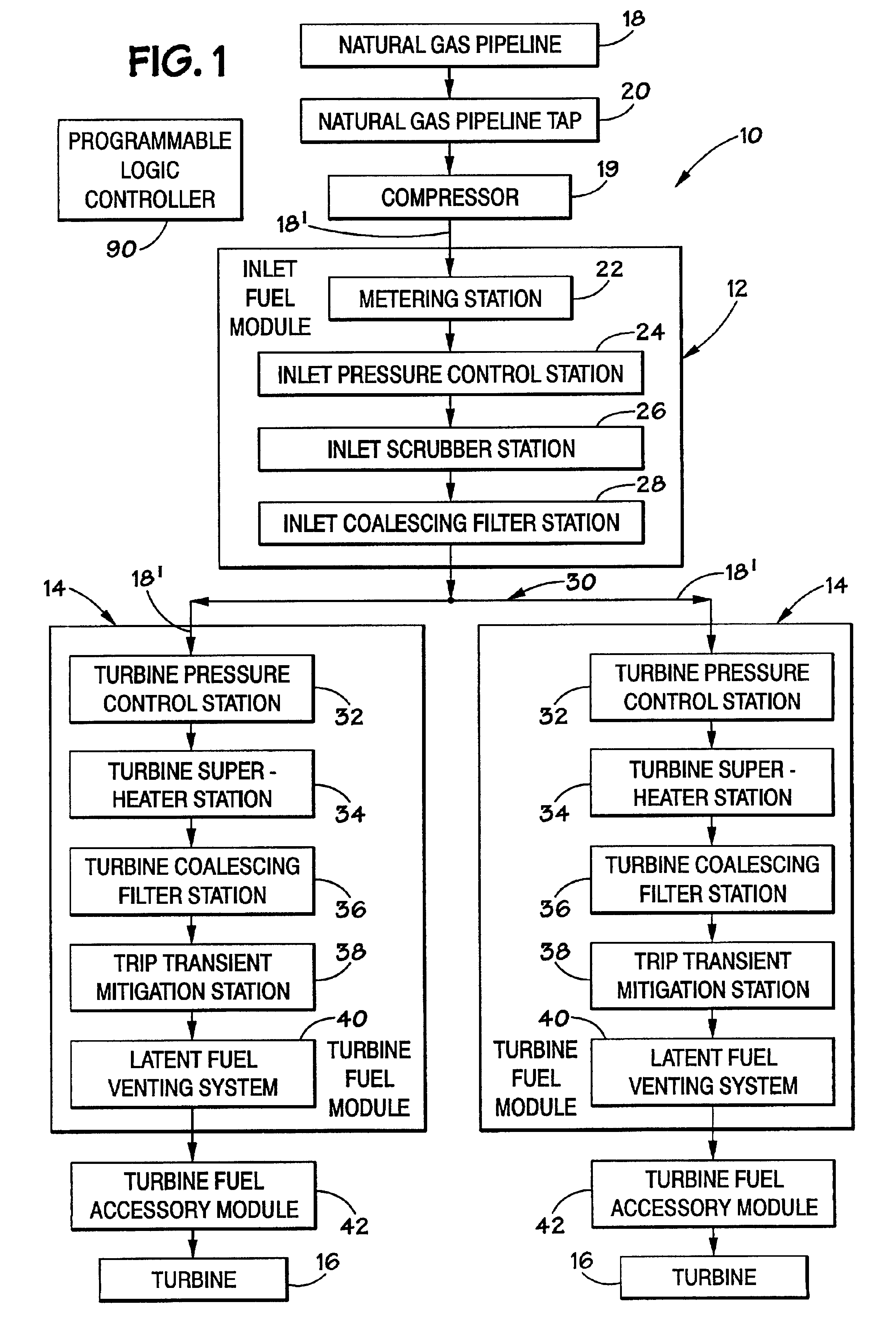
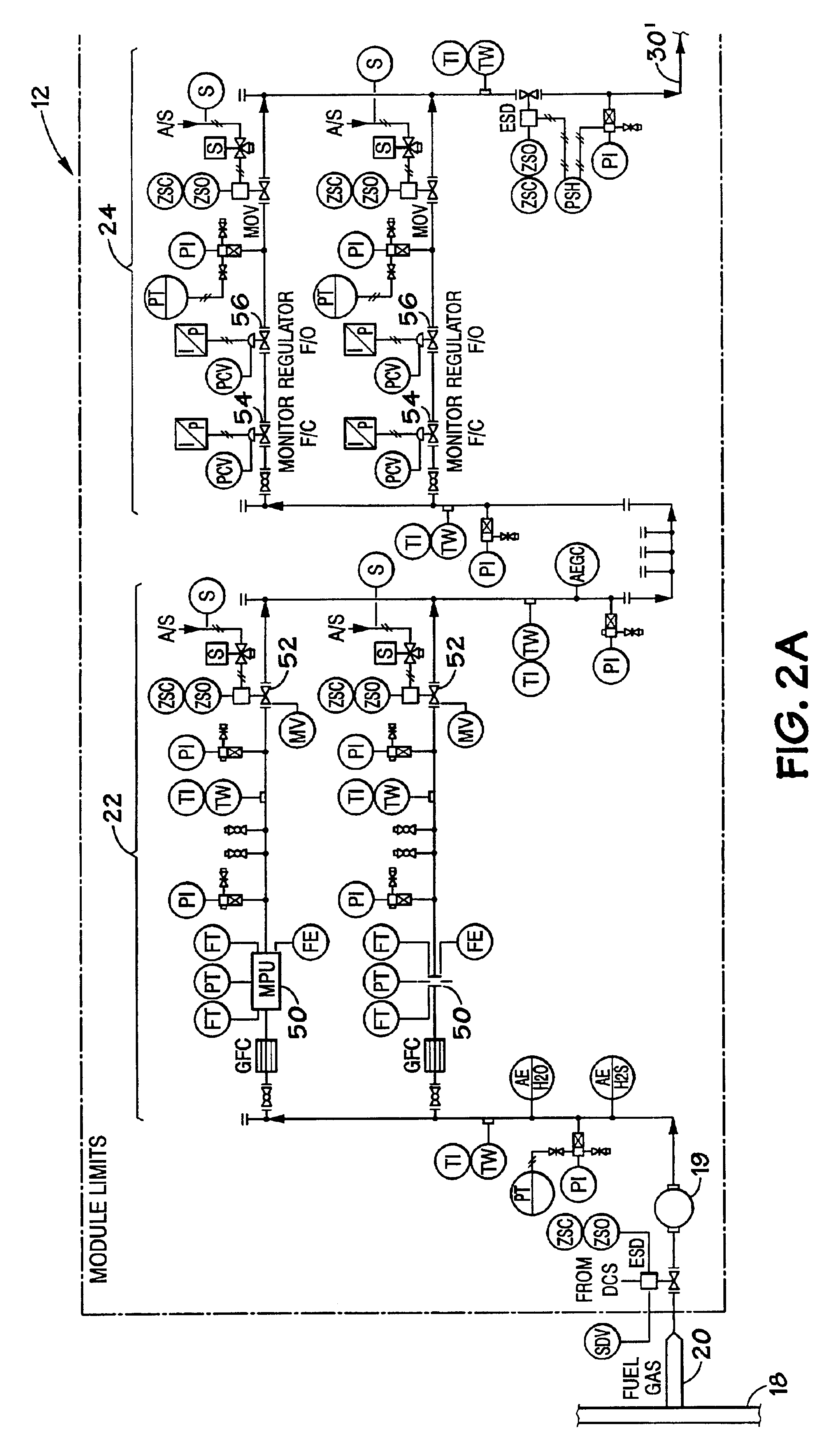
[0021]Referring to FIG. 1, the preferred embodiment of the fuel conditioning system 10 of the present invention has a modular design that includes an inlet fuel module 12 for the turbine plant, and a turbine fuel module 14 for each conventional turbine 16. The inlet fuel module 12 receives natural gas fuel from a conventional pressurized natural gas pipeline 18 via a conventional pipeline tap 20 provided by the operator of the pipeline. From the pipeline tap 20, the natural gas fuel 18′ travels, or flows, into the metering station 22 within the inlet fuel module 12, and the metering station 22 measures the amount of fuel received from the pipeline 18. From the metering station 22, the fuel then flows into the inlet pressure control station 24, which reduces the pressure of the fuel received from the pipeline 20. The fuel is then received by the inlet scrubber station 26, which removes liquids from the fuel. The fuel that leaves the inlet scrubber station 26 then flows into the inlet...


PUM


Abstract

A fuel conditioning system for a turbine plant may include an inlet fuel module followed by a turbine fuel module for each turbine, the modules being monitored and controlled by a programmable logic controller. The inlet fuel module may include a metering station, an inlet pressure control station, an inlet scrubber station, and an inlet coalescing filter station. Each turbine fuel module has a turbine pressure control station, a turbine super-heater station, and a turbine coalescing filter station. The fuel conditioning system may also include a trip transient mitigation system and a latent fuel venting system. The programmable logic controller collects data from all of the stations and systems as well as the turbine and then uses self-correcting algorithms to control the stations and systems. The programmable logic controller also stores the data collected and transmits the data to an off-site storage and verification center.

Description

RELATED APPLICATION[0001]This application claims the benefit of U.S. Provisional Patent Application Serial No. 60 / 309,413, filed Aug. 1, 2001, entitled “Modular Fuel Conditioning System”.BACKGROUND OF THE INVENTION[0002]1. Field of the Invention[0003]The present invention relates generally to fuel conditioning systems. More specifically, the present invention relates to fuel conditioning systems for natural gas fuel powered turbines.[0004]2. Description of the Related Art[0005]In the field of natural gas fuel powered turbines, the manufacturers of the turbines put very strict restrictions upon the quality of the fuel that can be used with their turbines. In some countries the fuel, provided from a pipeline supplying the turbine with fuel, does not comply with these restrictions. The fuel from the pipeline is typically at a higher pressure than that needed by the turbine with a tendency for variations in pressure. The fuel may also contain various contaminants such as moisture, liqui...

Claims


Application Information

Patent Timeline
Patent Type & Authority Patents(United States)
IPC IPC(8): F02C3/22F02C7/22F02C3/20F02C9/28F02C9/00F02C7/224F02C9/40F02C9/42
CPCF02C3/22F02C7/22F02C7/224F02C9/40F02C9/42F02C9/28F05D2270/303F05D2270/083
Inventor LOHN, PAUL
Owner PIPELINE CONTROLS
Learn More