Micro fluidic device for controlling flow time of micro fluid

a micro fluid and fluid flow technology, applied in the direction of process and machine control, instruments, transportation and packaging, etc., can solve the problems of large area of micro fluidic devices, and complex structure, and achieve simple structure and simple principle

Active Publication Date: 2005-06-07
INTELLECTUAL DISCOVERY CO LTD
View PDF6 Cites 23 Cited by
  • Summary
  • Abstract
  • Description
  • Claims
  • Application Information

AI Technical Summary

Benefits of technology

[0009]It is, therefore, an object of the present invention to provide a micro fluidic device that can delay a flow of fluid for a predetermined time by using a simple principle and a simple structure.

Problems solved by technology

However, since additional tubes and holes for draining air should be formed, the structure becomes very complicated.
Moreover, this method can hardly be applied to a case where more than three flow channels meet together in a confluence junction, and the area of the micro fluidic device is large due to the volume of the additional holes.
This method, either, does not prevent the generation of air bubbles and it should have additional tubes formed to drain air, thus making the structure complex and hardly applied to a case where more than two flow channels meet together.
Since the flow channels should be formed in three-dimensional, it is complicated and the generation of air bubbles at confluence junctions cannot be prevented.
All the above-mentioned technologies have shortcomings that they do not prevent the generation of air bubbles at confluence junctions and the structures and fabrication processes are complicated.
However, the delay time is just as short as two minutes, which is not sufficient for reactions, such as deoxyribonucleic acid (DNA) amplification, hybridization and antigen-antibody reaction, in the reaction chamber.
Moreover, the pressure barrier should be formed in three-dimensional and hydrophobic surface modification, the fabrication process is complicated.

Method used


Image

  • Micro fluidic device for controlling flow time of micro fluid
  • Micro fluidic device for controlling flow time of micro fluid
  • Micro fluidic device for controlling flow time of micro fluid

Examples


Embodiment Construction

[0032]Other objects and aspects of the invention will become apparent from the following description of the embodiments with reference to the accompanying drawings, which is set forth hereinafter. The embodiments of the present invention can be modified variously. Thus, the scope of the present invention should be construed not limited to the embodiments to be described herein. The embodiments are provided to better explain the present invention to those of ordinary skill in the art. The same reference number is given to the same element of the present invention, although it appears in different drawings. Further, the elements and areas of the drawings are drawn roughly only, and the scope of the present invention is not limited to the relative sizes and gaps in the drawings.

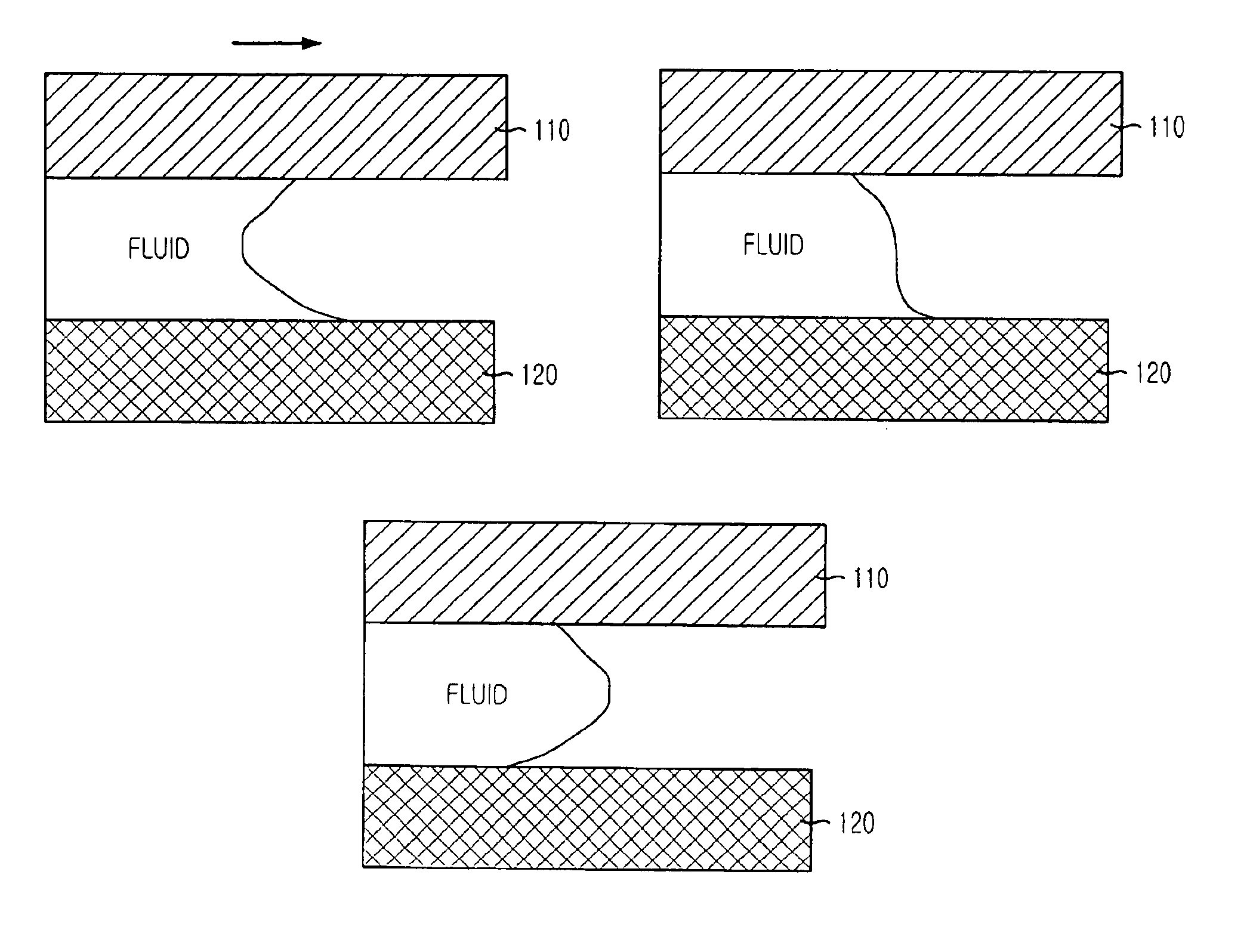
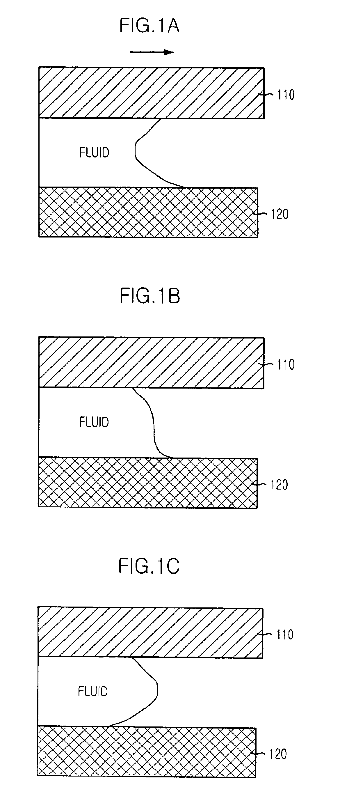
[0033]FIGS. 1A to 1C describes a principle of flowing of fluid based on a capillary phenomenon or a combination of a capillary pressure and external pressure. FIG. 1A shows a shape of the fluid at a line-end of ...


PUM


Abstract

Provided is a micro fluidic device that can control a flow time of micro fluid by using a capillary phenomenon. The micro fluidic device includes: a flow channel for flowing fluid, the flow channel being formed between a top substrate and a bottom substrate or between a top substrate, a bottom substrate, and a middle substrate; a flow blocking surface for stopping a flow of the fluid in the flow channel temporarily; and a hump for delaying the flow formed in the line of continuity with the flow blocking surface. The micro fluidic device of the present research can control the flow time in a simple manner.

Description

FIELD OF THE INVENTION[0001]The present invention relates to a micro fluidic device that can be applied to an automatic micro analysis system, such as biosensors, biochips and high throughput screening (HTS), and a combinatory chemistry system; and, more particularly, to a micro fluidic device that can delay a flow time of micro fluid in a micro fluidic network. These systems have a complicated micro fluidic network in which a plurality of flow channels are meeting and diverged. The micro fluidic network requires valves for stopping the flow of the fluid in each micro fluidic unit as well as pumps for making the fluid flow. Various phenomena occur in places where the flow channels meet or diverged.DESCRIPTION OF RELATED ART[0002]When two different micro fluids come across in a flow channel, one of the fluids passes a confluence junction first and the other fluid passes the confluence junction. In this process, air bubbles may be generated due to an air layer formed between the fluid...

Claims


Application Information

Patent Timeline
Patent Type & Authority Patents(United States)
IPC IPC(8): G05D7/01G05D7/00B01J19/00
CPCG05D7/0186Y10T137/2076Y10T137/2224B01J19/00
Inventor KIM, SUNG JINSHIN, YONG BEOMYANG, HAESIKLEE, DAE SIKKIM, KYU WONPARK, SE HOKIM, YUN TAE
Owner INTELLECTUAL DISCOVERY CO LTD
Why Eureka
Try Eureka