
High speed generator with high-power rotating rectifiers cooling system

a high-speed generator and rotating rectifier technology, applied in the direction of cooling/ventilation arrangement, magnetic circuit rotating parts, magnetic circuit shape/form/construction, etc., can solve the problems of electrical loss of electrical components within the generator, and achieve the effect of increasing the physical size of the diodes, increasing the power density of the diodes, and increasing the cooling efficiency

Inactive Publication Date: 2005-06-07
HONEYWELL INT INC
View PDF25 Cites 36 Cited by
  • Summary
  • Abstract
  • Description
  • Claims
  • Application Information

AI Technical Summary

Benefits of technology

[0009]The present invention provides increased cooling efficiency for the rotating rectifier diodes in a generator, including those with hybrid cooling systems in which dry cavities are included, which allows the diode power densities to increase without also increasing the physical size of the diodes, and allows a smaller diode package to be used for a given diode power density.

Problems solved by technology

In addition, some of the electrical components within the generator may generate heat due to electrical losses, and may thus be supplied with a cooling medium.

Method used


Image

  • High speed generator with high-power rotating rectifiers cooling system
  • High speed generator with high-power rotating rectifiers cooling system
  • High speed generator with high-power rotating rectifiers cooling system

Examples


Embodiment Construction

[0023]Before proceeding with the detailed description, it is to be appreciated that the present invention is not limited to use in conjunction with a specific type of electrical machine. Thus, although the present invention is, for convenience of explanation, depicted and described as being implemented in a brushless AC (alternating current) generator, it will be appreciated that it can be implemented in other AC generator designs needed in specific applications, and other electrical machines, such as various AC motor designs.

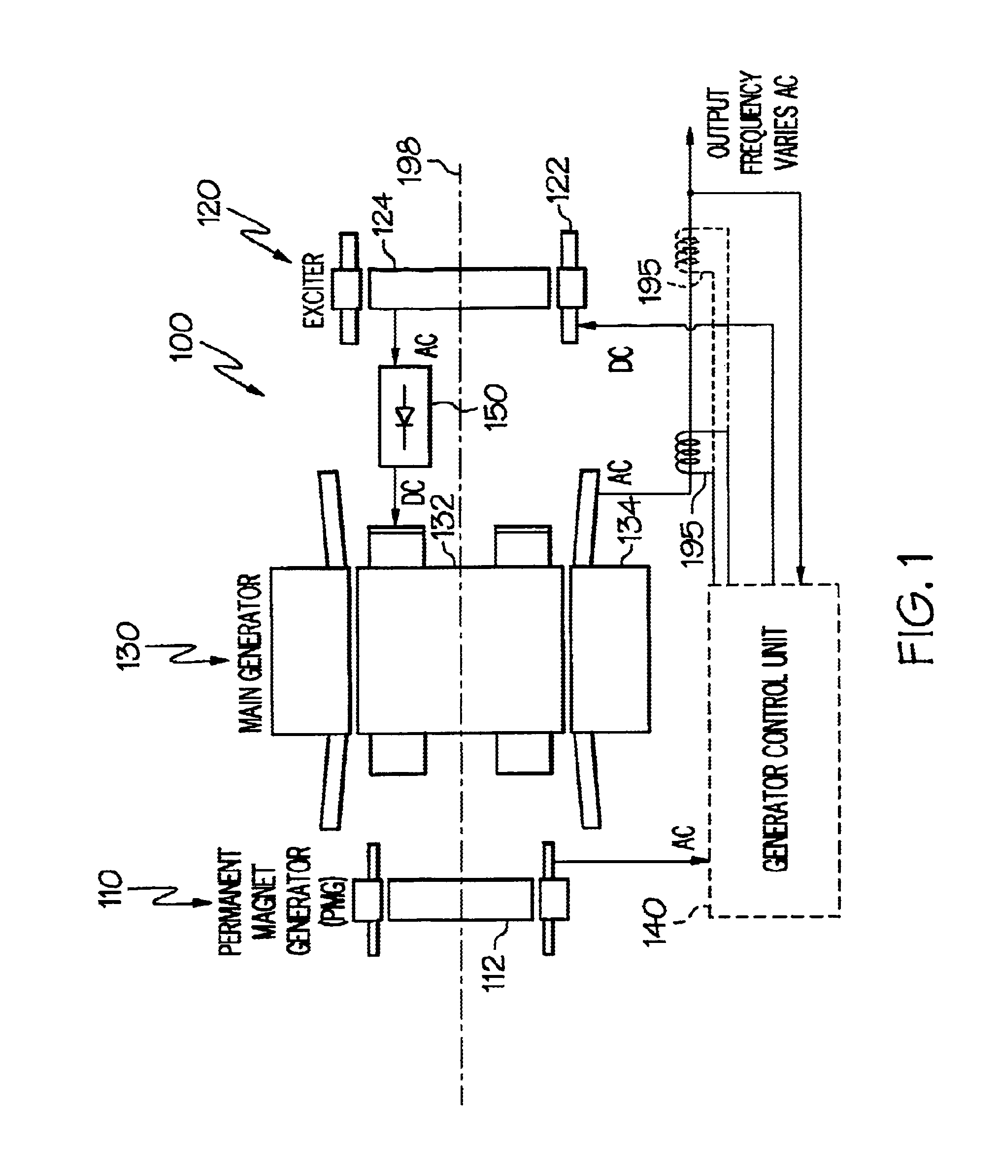
[0024]Turning now to the description, and with reference first to FIG. 1, a functional schematic block diagram of an exemplary high speed generator system 100 for aircraft, and which may include an embodiment of the present invention, is depicted. This exemplary generator system 100, which is commonly known as a brushless AC generator, includes a permanent magnet generator (PMG) 110, an exciter 120, a main generator 130, a generator control unit 140, and one or...


PUM


Abstract

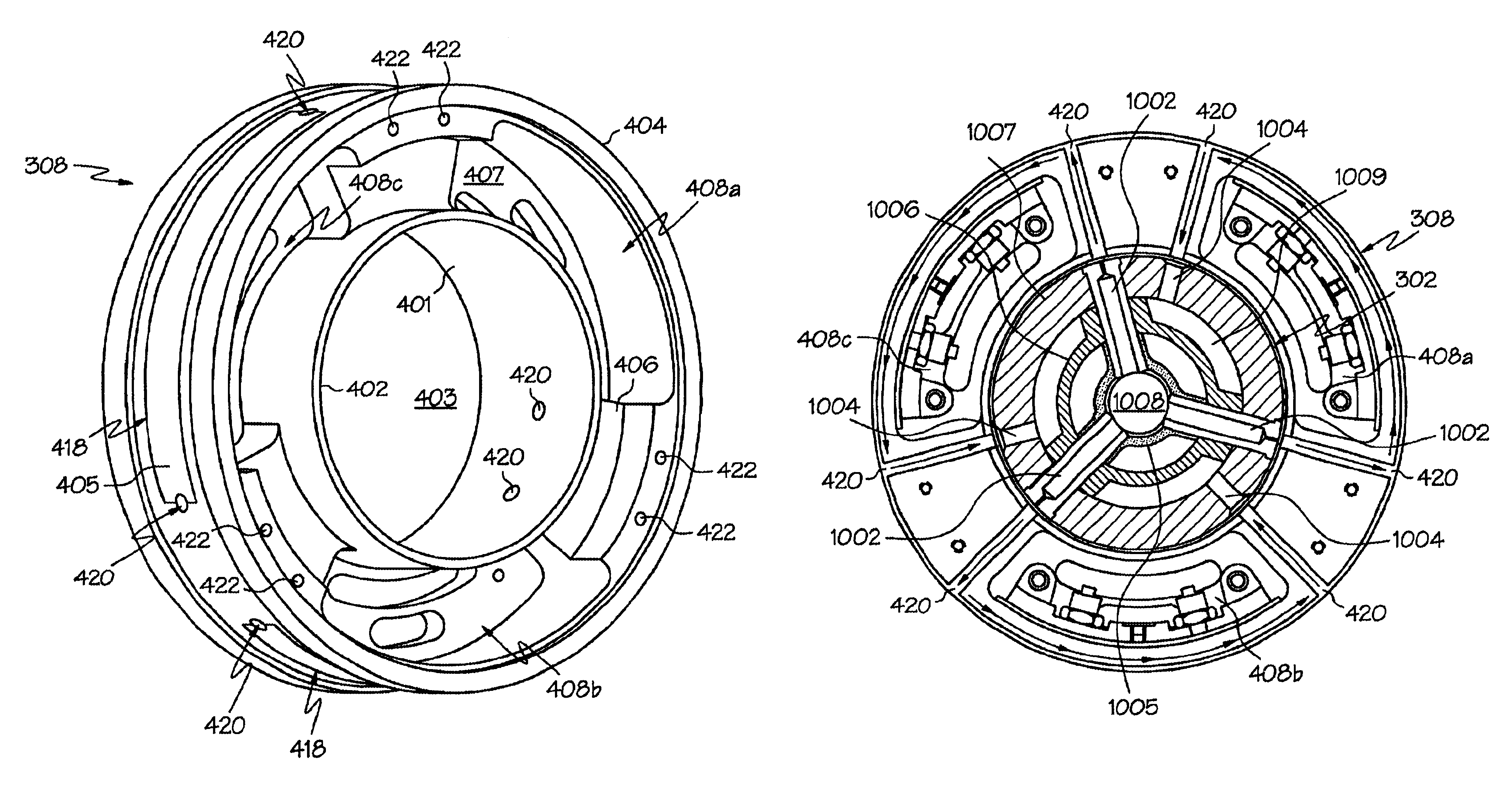
A rectifier hub and associated cooling method provide increased cooling efficiency for rotating rectifier diodes in a dry cavity generator. The rectifier hub has an inner and an outer circumferential surface and includes at least one pair of flow passages, and at least one flow channel. Each pair of flow passages extends between the hub inner and outer circumferential surfaces, and each flow channel is formed in the hub outer circumferential surface and couples the pair of flow passages in fluid communication with one another. This configuration allows a cooling medium to flow directly across the rectifier hub and cool the rectifier diodes mounted within drive cavities formed in the hub.

Description

STATEMENT REGARDING FEDERALLY SPONSORED RESEARCH OR DEVELOPMENT[0001]This invention was made with Government support under Agreement No. DTFR 53-99-H-0006 awarded by Federal Railroad Administration. The Government may have certain rights in this invention.FIELD OF THE INVENTION[0002]The present invention relates to high speed generators and, more particularly, to high speed generators having high-power rotating rectifiers mounted in dry cavities and intended for use with gas turbine engines.BACKGROUND OF THE INVENTION[0003]A generator system for a gas turbine engine, such as that found in aircraft, ships, and some terrestrial and space vehicles, may include three separate brushless generators, namely, a permanent magnet generator (PMG), an exciter, and a main generator. The PMG includes permanent magnets on its rotor. When the PMG rotates, AC currents are induced in stator windings of the PMG. These AC currents are typically fed to a regulator or a generator control device, which in...

Claims


Application Information

Patent Timeline
Patent Type & Authority Patents(United States)
IPC IPC(8): H02K11/04
CPCH02K11/042
Inventor DOHERTY, KIERANROGERS, SHANNONSCHERZINGER, WILLIAMSTOUT, DAVIDWADDELL, SIMONXU, MING
Owner HONEYWELL INT INC
Learn More