Method and apparatus for damping mechanical oscillations of a shaft in machine tools, manufacturing machines and robots

a technology of mechanical oscillation and shaft, which is applied in the direction of electrical controllers, programs, instruments, etc., can solve the problems of reduced processing accuracy, limited damping of resonance oscillations, and often produced undesired oscillations by modern machine tools, manufacturing machines or robots. good effect of mechanical shaft oscillation

Active Publication Date: 2005-06-07
SIEMENS AG
View PDF18 Cites 19 Cited by
  • Summary
  • Abstract
  • Description
  • Claims
  • Application Information

AI Technical Summary

Benefits of technology

[0012]According to another feature of the present invention, instead of a sensor and / or measuring system for measuring position values for the shaft, a sensor and / or measuring system may conceivably be used as well, for measuring the actual speed of the shaft. The actual speed of the shaft is then fed directly to the feedback elements as an input variable. The determination of the actual shaft speed by differentiation of the actual position value of the shaft can thus be eliminated by directly measuring the actual speed.
[0013]According to another feature of the present invention, in addition to or instead of the sensor and / or measurement system for measurement of the actual shaft position, further sensors and / or measurement systems can be used, especially those for measuring shaft acceleration and / or shaft speed, and the respective measured shaft variable or a calculated variable produced from measured variables is supplied as input variable to a respective one of sets of feedback elements, whereby each of the sets of feedback elements has at least one feedback element. By the use of not just one but multiple measured variables as input variables for a respective separate set of feedback elements, for example an actual position value as well as shaft acceleration, a particularly good damping of the mechanical shaft oscillations can be achieved.

Problems solved by technology

Modern machine tools, manufacturing machines or robots frequently produce undesired oscillations, particularly about the shafts and in particular the NC-shafts (numerical-control shafts) of the machine.
Such resonance produces undesirable chatter marks that mechanically strain the machine, and leads to a decrease in the processing accuracy.
Only a very limited damping of these resonance oscillations is possible with the position control means available.
This conventional approach is unsuitable for implementing an effective damping of the oscillations caused by mechanical resonance.
The result is inadequate machine dynamics and chatter marks, as well as the gain in the position controller being limited to just a small adjustable range.

Method used


Image

  • Method and apparatus for damping mechanical oscillations of a shaft in machine tools, manufacturing machines and robots
  • Method and apparatus for damping mechanical oscillations of a shaft in machine tools, manufacturing machines and robots
  • Method and apparatus for damping mechanical oscillations of a shaft in machine tools, manufacturing machines and robots

Examples


Embodiment Construction

[0015]The depicted embodiment is to be understood as illustrative of the invention and not as limiting in any way. It should also be understood that the drawings are not necessarily to scale and that the embodiments are sometimes illustrated by graphic symbols, phantom lines, diagrammatic representations and fragmentary views. In certain instances, details which are not necessary for an understanding of the present invention or which render other details difficult to perceive may have been omitted.

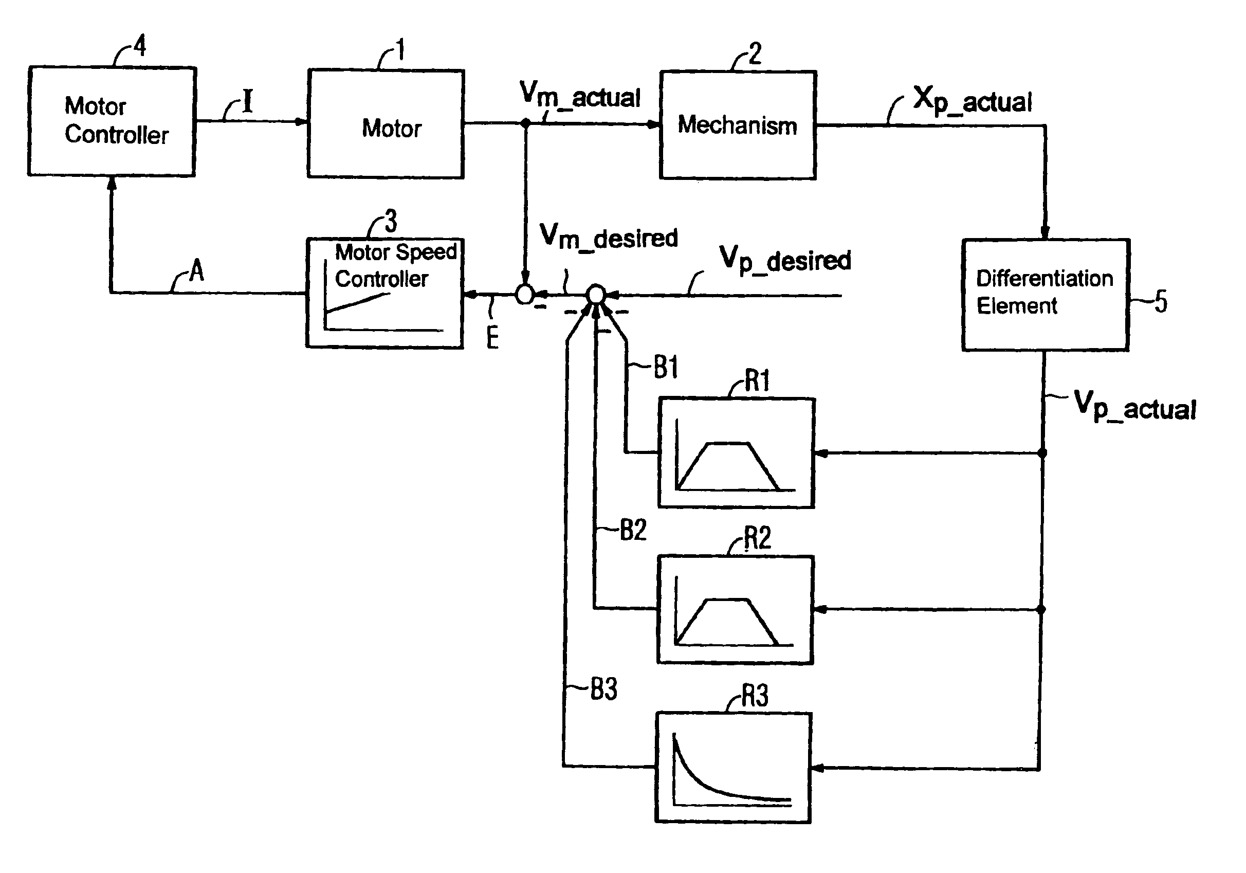
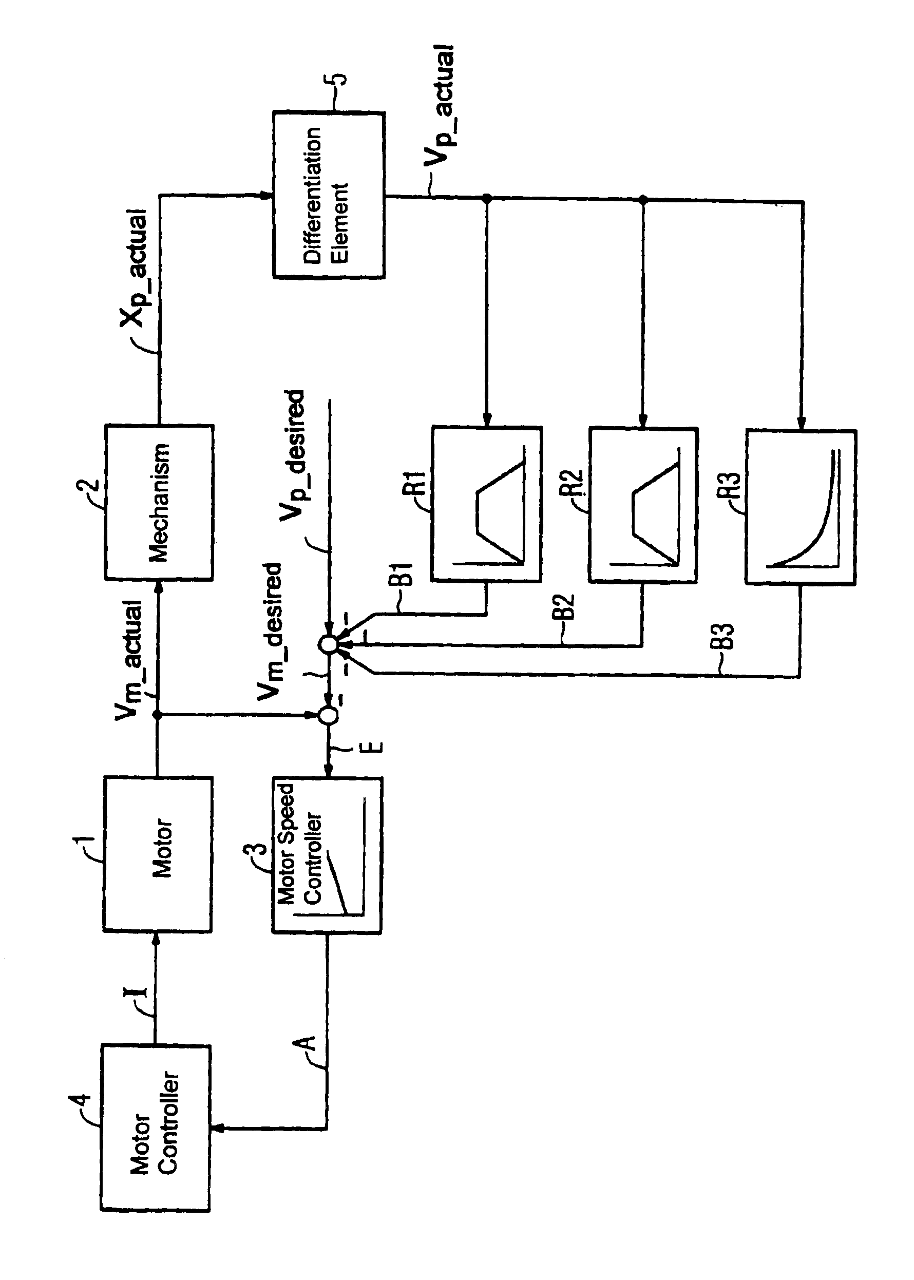
[0016]Turning now to FIG. 1, there is shown a schematic block diagram illustrating the components of the subject matter of the present invention. A motor 1 drives a not shown shaft of a machine via a mechanism 2. An actual speed Vm—actual of the motor 1 and an actual position value Xp—actual is measured by a suitable measuring system. The motor speed Vm—actual is controlled by a motor speed controller 3, which has the difference between the motor speed Vm—actual and the desired motor speed...


PUM


Abstract

Damping of mechanical oscillation in a shaft that is provided by feedback wherein the output signals of multiple feedback devices are negatively coupled and added to a desired speed signal of a motor speed controller of the driving motor is disclosed. At least one sensor and/or measuring system can be provided for measuring an actual position value. The actual speed of the shaft can be determined by differentiation from the shaft position value measurements or by integration from shaft acceleration measurements. The measured or actual speed of the shaft can be supplied as an input signal to each feedback element. Each feedback element is specifically tuned to an oscillation frequency range of the shaft that is to be damped. The invention provides an easy and cost-effective way of damping mechanical oscillations that have limited frequency ranges.

Description

CROSS-REFERENCES TO RELATED APPLICATIONS[0001]This application claims the priority of German Patent Application, Ser. No. 102 46 093.0, filed Oct. 2, 2002, pursuant to 35 U.S.C. 119(a)-(d), the disclosure of which is incorporated herein by reference.BACKGROUND OF THE INVENTION[0002]The present invention relates to a method and apparatus for damping mechanical oscillations of shafts of a machine tool, manufacturing machine or robot by providing feedback elements that apply a negative feedback output signal from each feedback element to the desired rotational speed value of a speed controller for a motor driving the shaft.[0003]Modern machine tools, manufacturing machines or robots frequently produce undesired oscillations, particularly about the shafts and in particular the NC-shafts (numerical-control shafts) of the machine. It is to be understood by persons skilled in the art that the term “machine” is used here in a generic sense and the principles described in the following descr...

Claims


Application Information

Patent Timeline
Patent Type & Authority Patents(United States)
IPC IPC(8): F16F15/02F16F15/00G05B19/404
CPCF16F15/005F16F15/02G05B19/404G05B2219/41121G05B2219/37493G05B2219/37525
Inventor KUNZEL, STEFANREICHEL, THEOSCHAFERS, ELMARUHLICH, ANDREAS
Owner SIEMENS AG
Why Eureka
Try Eureka