
Discharging apparatus for liquid crystal display

Inactive Publication Date: 2005-06-07
LG DISPLAY CO LTD
View PDF5 Cites 206 Cited by
  • Summary
  • Abstract
  • Description
  • Claims
  • Application Information

AI Technical Summary

Benefits of technology

[0012]One aspect of the present invention is a discharging apparatus for a liquid crystal display that is capable of simplifying a structure of a liquid crystal display panel.

Problems solved by technology

However, an existing problem of active matrix LCD's is that a voltage across a liquid crystal cell slowly decreases just after power to the device is turned off.
This slow voltage decrease causes an undesirable residual image in the display after the display device is turned off (after power-off).
However, the conventional power-off discharge circuit has a drawback in that the liquid crystal display panel has a complicated structure since the discharge circuit 12 is provided on the liquid crystal display panel for each gate line GL.
Moreover, since both the voltage supply line VDDL and the ground line GNDL for each discharge circuit 12 are formed on the liquid crystal display panel, the corresponding increase in the number of electrode lines complicates the liquid crystal panel display structure and adds to manufacturing complexity and costs.

Method used


Image

  • Discharging apparatus for liquid crystal display
  • Discharging apparatus for liquid crystal display
  • Discharging apparatus for liquid crystal display

Examples


Embodiment Construction

[0023]Reference will now be made in detail to the preferred embodiments of the invention, examples of which are illustrated in the accompanying drawings. Whenever possible, the same reference numbers will be used throughout the drawings to refer to the same or like parts.

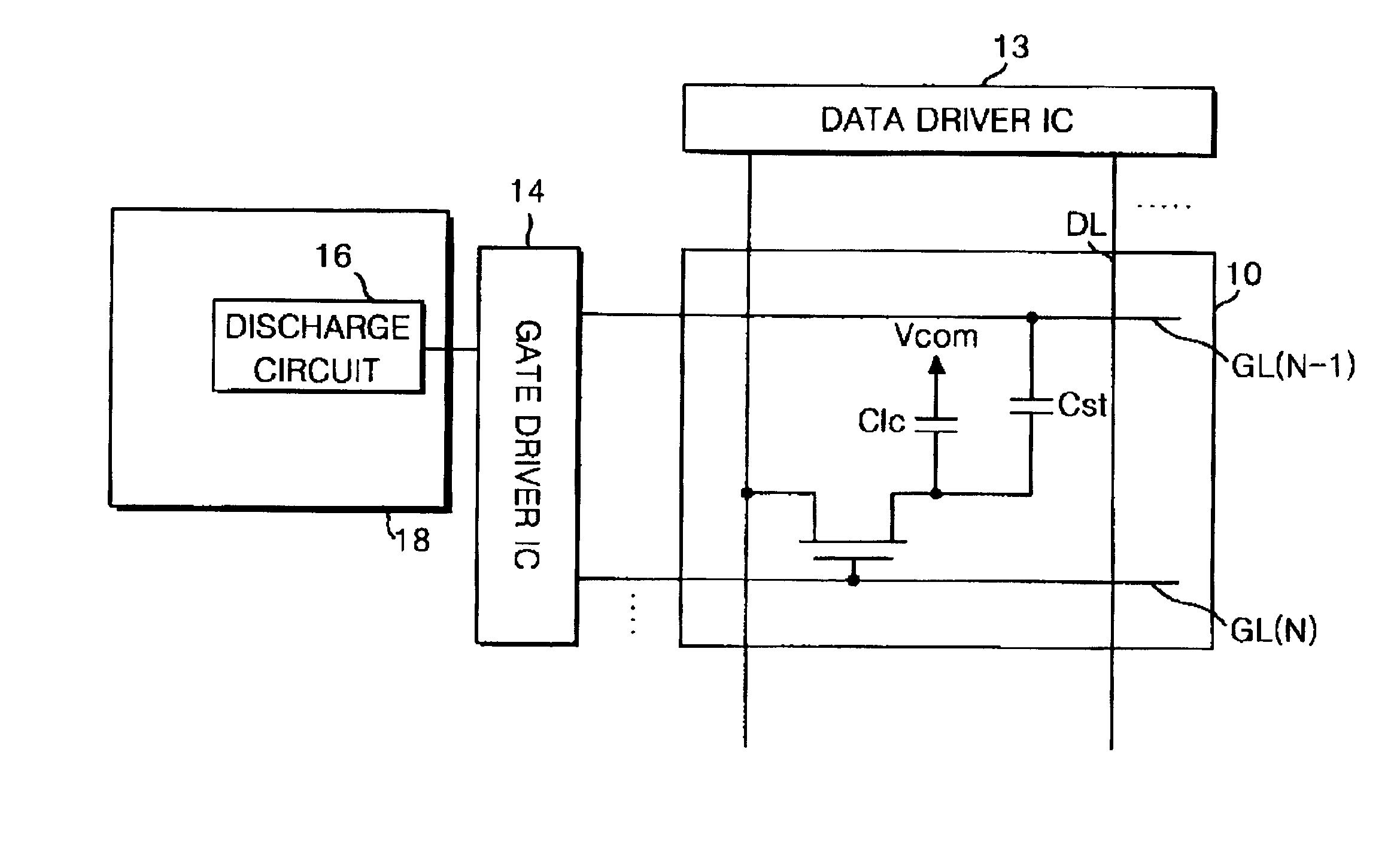
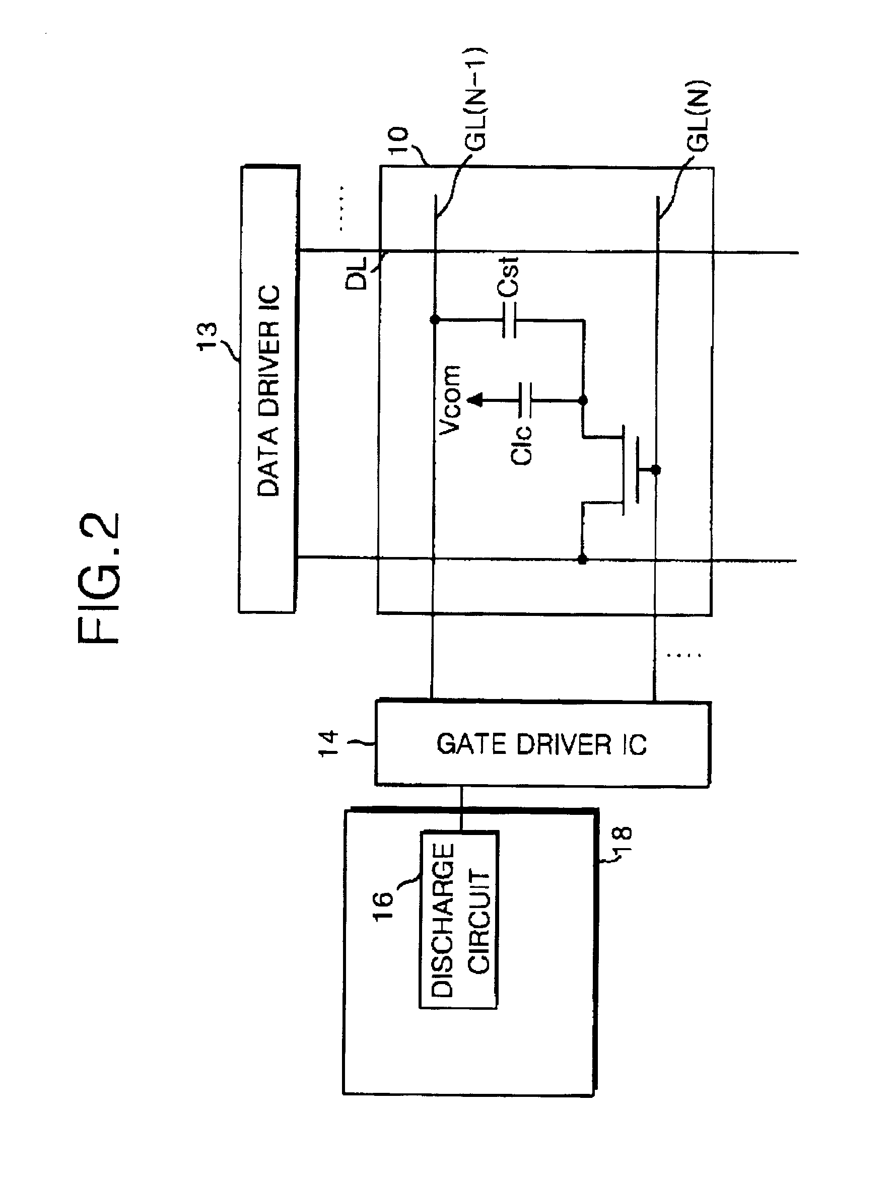
[0024]Referring to FIG. 2, there is shown a liquid crystal display (LCD) including a discharge circuit according to an embodiment of the present invention. The LCD includes a liquid crystal display panel 10 for displaying a picture, a data driver integrated circuit (IC) 13 for driving data lines DL of the liquid crystal display panel 10, a gate driver IC 14 for driving gate lines GL of the liquid crystal display panel 10, and a discharge circuit 16 connected to the gate driver IC 14.

[0025]FIG. 2 shows an exemplary circuit of one pixel of a plurality of pixels that are included in the liquid crystal display panel 10. As shown in FIG. 2, each pixel circuit may include a TFT arranged at intersections between a gate lin...


PUM


Abstract

A discharging apparatus for a liquid crystal display is provided for substantially reducing a residual image upon power-off. In the apparatus, a gate driver integrated circuit selectively applies first and second gate voltages to gate lines of the display. A discharge circuit is coupled to the gate driver integrated circuit and senses a power-off state of a power supply line. When a power-off state is sensed, a short-circuit if formed between the first gate voltage supply line and the second gate voltage supply line, thereby discharging voltages on the gate lines. Accordingly, a gate low voltage relative gate high (pixel turn-on) voltage is discharged upon power-off to define a discharge path via the gate line, thereby rapidly discharging electric charges charged in the liquid crystal display panel.

Description

[0001]This application claims the benefit of Korean Patent Application No. P00-79984, filed on Dec. 22, 2000, which is hereby incorporated by reference.BACKGROUND OF THE INVENTION[0002]1. Field of the Invention[0003]This invention relates to a thin film transistor (TFT) liquid crystal display, and more particularly, to a discharging apparatus for a liquid crystal display for substantially reducing a residual image upon power-off.[0004]2. Description of the Related Art[0005]Generally, a liquid crystal display (LCD) of active matrix driving system uses thin film transistors (TFT's) as switching devices to display a natural-like moving picture. Since such an LCD device can be made smaller than an existing Brown tube, it has been widely used as a monitor for personal or notebook computers, as well as in office automation equipment, such as copy machines, facsimile machines, and the like; and in portable equipment such as cellular phones and pagers, and the like.[0006]An active matrix LC...

Claims


Application Information

Patent Timeline
IPC IPC(8): G09G3/36G02F1/133
CPCG09G3/3648G09G2330/027G09G2320/0257G09G2310/0245G02F1/133
Inventor EU, JUNG-TAECK
Owner LG DISPLAY CO LTD
Features
  • Generate Ideas
  • Intellectual Property
  • Life Sciences
  • Materials
  • Tech Scout
  • Unparalleled Data Quality
  • Higher Quality Content
  • 60% Fewer Hallucinations
Learn More