Cold plate assembly

Active Publication Date: 2005-06-07
RAYTHEON CO
View PDF9 Cites 44 Cited by
  • Summary
  • Abstract
  • Description
  • Claims
  • Application Information

AI Technical Summary

Benefits of technology

[0007]It is therefore an object of this invent

Problems solved by technology

Liquid cooling the cold plate requires fluid couplings which are prone to leak, are expensive, and have a high life cycle cost.
Heat sinks or cold plates with added graphite and/or aluminum to incre

Method used


Image

  • Cold plate assembly
  • Cold plate assembly
  • Cold plate assembly

Examples


Example

[0044]Aside from the preferred embodiment or embodiments disclosed below, this invention is capable of other embodiments and of being practiced or being carried out in various ways. Thus, it is to be understood that the invention is not limited in its application to the details of construction and the arrangements of components set forth in the following description or illustrated in the drawings.

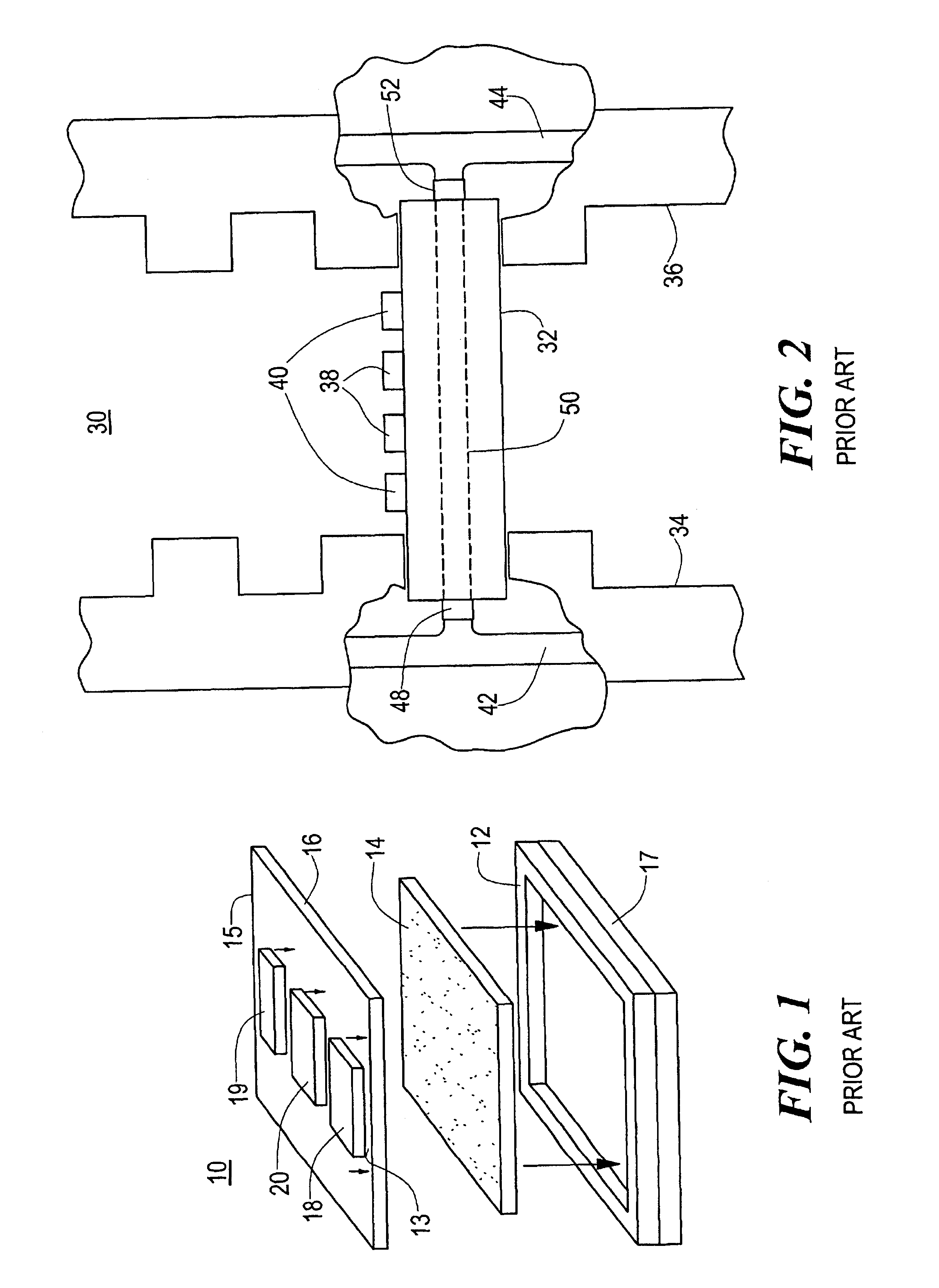
[0045]As explained in the Background section above, one key parameter governing the RF performance of a phased array radar system is the temperature gradient between heat sources, such as power amplifiers. Prior art cold plate 10, FIG. 1 is cooled on edges 13 and 15 typically by cooling manifolds (not shown). Cold plate 10 includes skins 16 and 17 and graphite core 14 which is embedded within aluminum body 12. Because high conductivity graphite core 14 extends throughout a substantial portion of aluminum body 12, the overall cooling efficiency of cold plate 10 is improved. However, this des...


PUM


Abstract

An edge cooled graphite core aluminum cold plate for use in phased array radar systems, the cold plate including opposing aluminum skins, and a core layer sandwiched between the opposing aluminum skins. The core layer includes graphite surrounded by an aluminum body. The aluminum body includes inwardly directed tabs extending from opposing cooled edges of the cold plate, the inwardly directed aluminum tabs having orifices therethrough. The opposing aluminum skins also includes orifices therethrough aligned with the orifices in the tabs of the aluminum body to reduce the conductivity of the cooled edges of the cold plate thus reducing the temperature gradient between edge mounted heat sources and inwardly mounted heat sources without adversely affecting the structural integrity of the graphite core layer.

Description

FIELD OF THE INVENTION[0001]This invention relates to a cold plate assembly and, in one example, to an edge cooled cold plate assembly for use in phased array radar systems.BACKGROUND OF THE INVENTION[0002]In some applications, it is not only important that heat sources such as integrated circuits be cooled, it is also important that the temperature gradient between any two heat sources be minimized. For example, one key parameter governing the radio frequency (RF) performance of a phased array radar system is the temperature gradient between heat sources, such as power amplifiers, in the transmit / receive (T / R) modules of the system. The power amplifiers in these T / R modules are mounted on a cold plate or heat sink which dissipates the heat from the power amplifiers. Because the distance from each power amplifier to the cooled edge of the cold plate varies, the power amplifiers which are located the greatest distance from the cooled edge of the cold plate (e.g., the interior mounted...

Claims


Application Information

Patent Timeline
IPC IPC(8): F28F3/12F28F3/00F28F21/08F28F21/00F28F21/02H01L23/373H01L23/34H01Q21/00H05K7/20G01S13/02G01S13/00G01S7/03
CPCF28F3/12F28F21/02F28F21/084H01L23/373H01Q21/0006G01S7/032G01S2013/0254H01L2924/0002H01L2924/00
Inventor MCCORDIC, CRAIG H.LOMBARDO, STEVEN M.ELLSWORTH, JOSEPH R.
Owner RAYTHEON CO
Why Eureka
Try Eureka