Resonant converter with phase delay control

a phase delay control and converter technology, applied in the field of resonant converters, can solve the problems of increasing hard switching losses in a typical pwm converter, affecting the efficiency of an input power supply, and generating greater electromagnetic interference (emi), so as to improve feedback control, high switching frequency, and high efficiency

Inactive Publication Date: 2005-06-07
INFINEON TECH AMERICAS CORP
View PDF21 Cites 52 Cited by
  • Summary
  • Abstract
  • Description
  • Claims
  • Application Information

AI Technical Summary

Benefits of technology

[0013]According to the present invention, a resonant power converter is provided that is controlled using a phase delay control to obtain improved feedback control while maintaining high efficiency. The res

Problems solved by technology

Typically, however, higher frequency switching in PWM converters results in increased switching losses and greater electromagnetic interference (EMI) being produced.
Typically, the switching losses occur because the switches are controlled to switch while conducting a current or bearing a voltage, resulting in “hard switching.” The hard switching losses in a typical PWM converter tend to increase with the switching frequency.
In addition, the EMI generated by hard switching, especially at high frequencies, can become a major factor that affects the efficiency of an input power supply through a reduced power factor.
In addition, the oscillatory nature of the input in a resonant converter permits a control scheme to shape the input current

Method used


Image

  • Resonant converter with phase delay control
  • Resonant converter with phase delay control
  • Resonant converter with phase delay control

Examples


Embodiment Construction

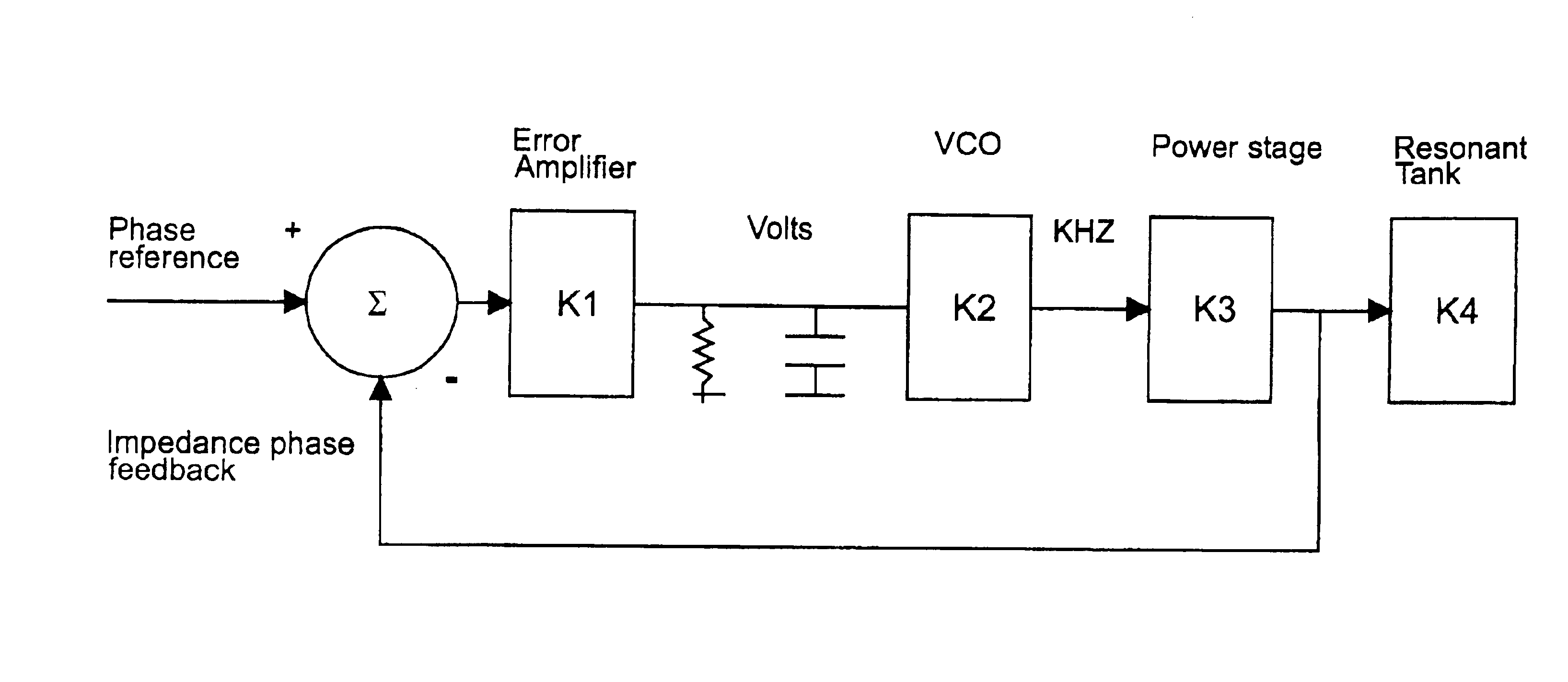
[0049]The present invention provides a resonant converter with a phase delay control implemented in an IC to obtain high efficiency and broad output range while reducing EMI. The phase delay control is implemented with a feedback arrangement that provides a current sense to determine a phase angle error measurement. The phase angle error measurement, derived from a comparison with a reference phase angle, is used to control a VCO that can modify a switching frequency to adjust the phase angle of the resonant tank voltage and current.

[0050]Referring to FIGS. 8-13, graphical illustrations of the relationship between power output, switching frequency and phase angle are provided for series, parallel and LCC resonant converters. In FIGS. 8, 10 and 12, the relationship between the output power and phase angle is substantially linear over a broad range of phase angles for each of the several types of resonant converters. In contrast, however, FIGS. 9, 11 and 13 illustrate that the power o...


PUM


Abstract

A phase delay control for a power converter operates with a phase locked loop and current sense feedback to provide improved control stability and dynamic output range. The phase lock loop includes a voltage controlled oscillator that is controlled based on an error signal derived from a phase of the power converter output. The error signal applied to the voltage controlled oscillator produces a shift in switching frequency for the converter to drive the error to zero. The power converter includes an LCC resonant circuit to manipulate resonant electrical energy to improve switching speed and power density.

Description

RELATED APPLICATIONS[0001]This application is based on and claims priority to U.S. Provisional Application No. 60 / 361,908, filed on Mar. 1, 2002, by Thomas Ribarich, entitled Resonant Mode Controller IC. and is a continuation-in-part application of application Ser. No. 10 / 316,248, filed Dec. 10, 2002, entitled Resonant Converter With Phase Delay Control, and is based on and claims benefit of U.S. Provisional Application No. 60 / 339,308, filed Dec. 12, 2001, entitled Resonant Converter With Phase Delay Control, to which a claim of priority is hereby made. The subject matter and disclosure of both applications being incorporated herein.BACKGROUND OF THE INVENTION[0002]1. Field of the Invention[0003]The present invention relates generally to resonant power converters, and relates more particularly to resonant power converters that are controlled with a phase delay control configuration.[0004]2. Description of the Related Art[0005]Many types of power converters are well known, in particu...

Claims


Application Information

Patent Timeline
IPC IPC(8): H02M7/5387H02M3/335H02M3/24
CPCH02M3/33569H02M7/523Y02B70/1433Y02B70/10H02M3/33571H02M3/01
Inventor RIBARICH, THOMAS J.
Owner INFINEON TECH AMERICAS CORP
Why Eureka
Try Eureka