
Wireless enhancer using a switch matrix

a switch matrix and enhancer technology, applied in repeater circuits, line-transmission, electrical apparatus, etc., can solve the problems of reducing the throughput of data between the bts and terminals by at least half, and the enhancer will not be transparent to the bts and terminals, so as to maximize the mutual isolation of the switch matrix and enhance the effect of the switch matrix

Inactive Publication Date: 2005-06-07
CISCO TECH INC
View PDF9 Cites 58 Cited by
  • Summary
  • Abstract
  • Description
  • Claims
  • Application Information

AI Technical Summary

Benefits of technology

[0009]In another example of the present disclosure, the switch matrix is further enhanced by including four controlled amplifiers to attenuate signal leakage from the switches of the switch matrix. The controlled amplifier can be a low noise amplifier, a power amplifier, or even a double pole single throw switch.
[0010]In another example of the present disclosure, a synthesizer is used to produce local oscillator frequencies for use by the receiver sub-system and the transmitter sub-system. The synthesizer can also be enhanced by including several pairs of switches and amplifiers arranged in such a way to further isolate local oscillator frequencies generated by the synthesizer.
[0011]One example of the enhancer disclosed is an enhancer using time division duplex technology, and contains a donor antenna and a service antenna. The donor antenna is designed to be a patch antenna facing the BTS direction, while the service antenna can be a dipole antenna lying on the same plane as the patch antenna. Both the patch and dipole antennas have a null point in their radiation patterns along the vertical direction so that such an arrangement will maximize their mutual isolation.

Problems solved by technology

Its drawback is that the enhancer will not be transparent to the BTS and terminals, and the data throughputs between the BTS and terminals are reduced at least by half.

Method used


Image

  • Wireless enhancer using a switch matrix
  • Wireless enhancer using a switch matrix
  • Wireless enhancer using a switch matrix

Examples


Embodiment Construction

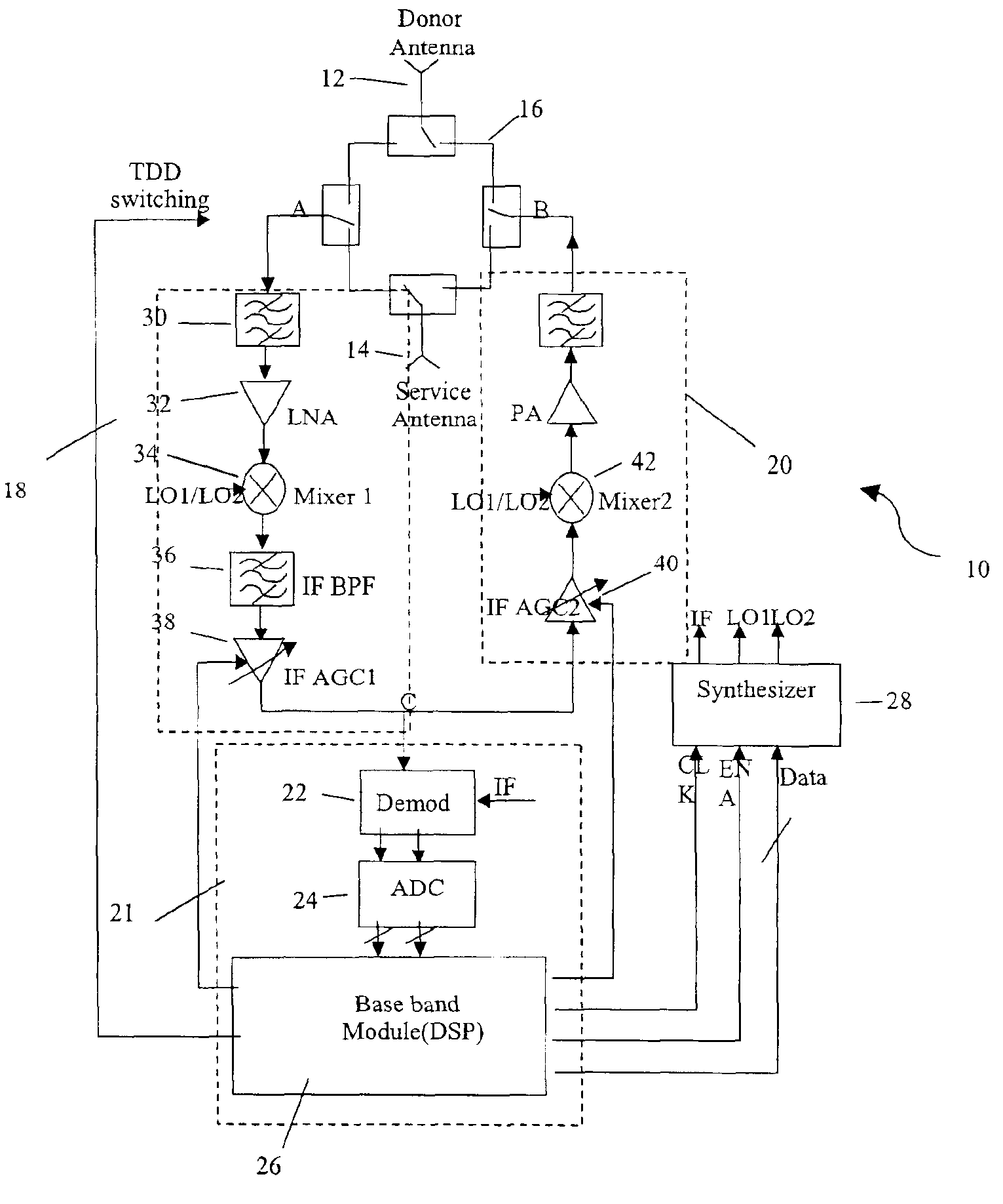
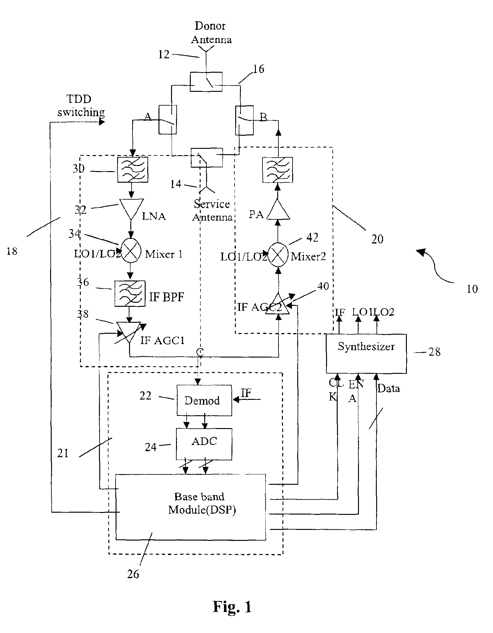
[0021]FIG. 1 illustrates a schematic of an enhancer 10 according to one example of the present disclosure. The components of the enhancer includes a donor antenna 12, a service antenna 14, a switch matrix 16, a receiver sub-system 18, a transmitter sub-system 20, a demodulator subsystem 21 which contains a demodulator 22, an analog-to-digital converter (ADC) 24, and a base band module (DSP) 26, and a synthesizer sub-system 28. The switch matrix 16 is controlled by switch signals that are derived from the TDD switch timing information provided by the DSP 26. Essentially, the switch matrix 16 makes appropriate connection arrangements for forward and reverse link communications to “switch in” corresponding either the donor antenna or the service antenna on one hand, and the receiver sub-system or the transmitter sub-system on the other hand. For example, Table 1 illustrates the expected connections for the input port A for the receiver sub-system 18 and the output port B for the transm...


PUM


Abstract

An improved enhancer is disclosed which uses a switch matrix to increase the isolation between two antennas. For either an reverse link or forward link communication, the enhancer has a first antenna for receiving an incoming signal, and a receiver sub-system that amplifies and converts the incoming signal from the first antenna to a first predetermined frequency band. The enhancer further has a demodulator coupled to the receiver sub-system for demodulating the converted signal, and detecting timing information thereof. Also contained in the enhancer is a transmitter sub-system operable with the receiver sub-system that converts the signal from the receiver subsystem to a second predetermined frequency band and further amplifies the signal. After the signal is thus enhanced, a second antenna is used for further transmitting the amplified signal from the transmitted sub-system. The switch matrix controls connection switching among the first antenna, the second antenna, the transmitter sub-system, and the receiver sub-system, wherein the connection switching of the switch matrix is made based on the timing information detected by the demodulator and based on whether the incoming signal comes from a terminal or a base transceiver station.

Description

BACKGROUND OF THE INVENTION[0001]The present disclosure relates generally to communication radio hardware and software, and more particularly, to the repeater or enhancer used in wireless communication systems.[0002]A repeater or enhancer is a radio apparatus that is used in wireless communication systems to boost or enhance radio signal strength in order to extend the radio coverage. An enhancer typically includes a donor antenna, a service antenna, and an electronic circuit that performs signal reception, amplification, and re-transmission. For the forward link (or down link) communications from a base transceiver station (BTS) to a terminal such as a mobile station, an enhancer receives a signal from the BTS through the donor antenna, enhances and re-transmits the signal to the intended terminals with the service antenna. Similarly for the reverse link (or up link) communications from the terminal to the BTS, the enhancer receives a signal from the terminal through the service an...

Claims


Application Information

Patent Timeline
Patent Type & Authority Patents(United States)
IPC IPC(8): H04B7/14H04B7/155
CPCH04B7/15571
Inventor JIN, HANGXU, GUANGHANXU, XINGUANG
Owner CISCO TECH INC
Features
  • Generate Ideas
  • Intellectual Property
  • Life Sciences
  • Materials
  • Tech Scout
  • Unparalleled Data Quality
  • Higher Quality Content
  • 60% Fewer Hallucinations
Learn More