Method of determining data transfer speed in data transfer apparatus

a data transfer apparatus and data transfer technology, applied in the field of determining the data transfer speed, can solve the problems of preventing the improvement of transfer efficiency, affecting the efficiency of data transfer, and affecting the detection of analog level bias signals

Inactive Publication Date: 2005-06-07
SOCIONEXT INC
View PDF26 Cites 13 Cited by
  • Summary
  • Abstract
  • Description
  • Claims
  • Application Information

AI Technical Summary

Benefits of technology

[0009]It is a first object of the present invention to provide a method of det

Problems solved by technology

Therefore, in a poor use environment which may involve an instable power supply, and so on, an error is likely to occur in the detection of the a

Method used


Image

  • Method of determining data transfer speed in data transfer apparatus
  • Method of determining data transfer speed in data transfer apparatus
  • Method of determining data transfer speed in data transfer apparatus

Examples


Embodiment Construction

[0024]A data transfer apparatus in one embodiment of the present invention will hereinafter be described with reference to the drawings.

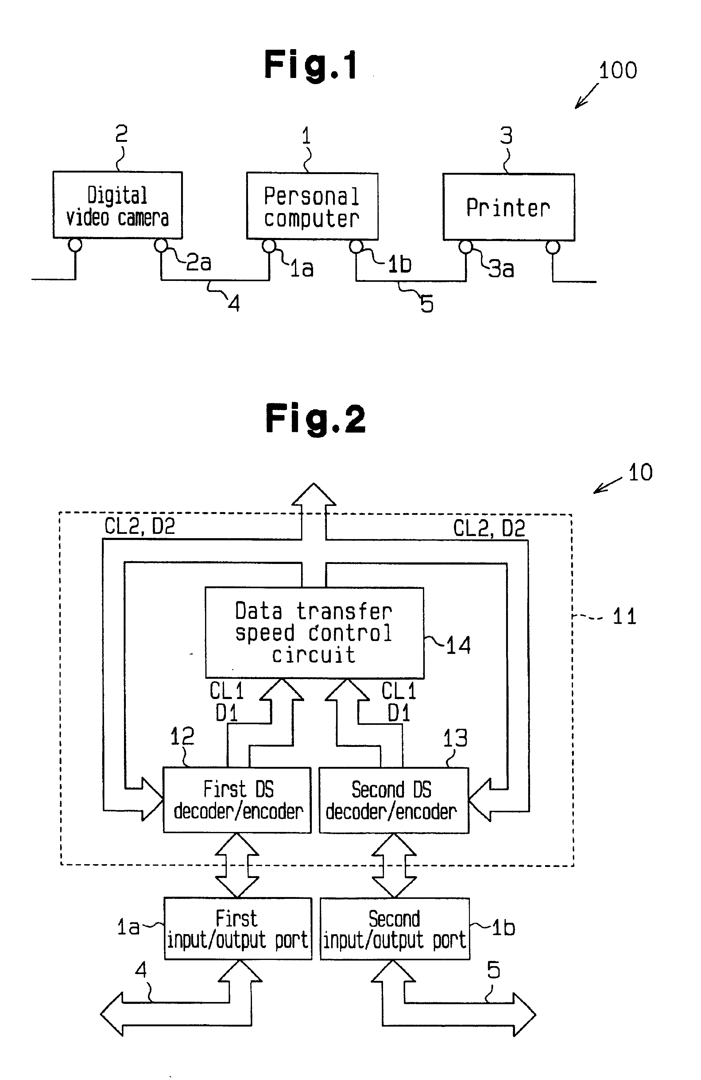
[0025]As illustrated in FIG. 1, a data transfer system 100 in conformity to the IEEE1394 protocol includes a personal computer 1, a digital video camera 2, and a printer 3. Each of the personal computer 1, digital video camera 2 and printer 3 includes an interface device for performing a data transfer in conformity to the IEEE1394 protocol, and is interconnected via IEEE1394 bus cables 4, 5 to constitute a daisy chain type bus topology. More specifically, a first input / output port 1a of the personal computer 1 is connected to an input / output port 2a of the digital video camera 2 via the bus cable 4, while a second input / output port 1b of the personal computer 1 is connected to an input / output port 3a of the printer 3 via the bus cable 5.

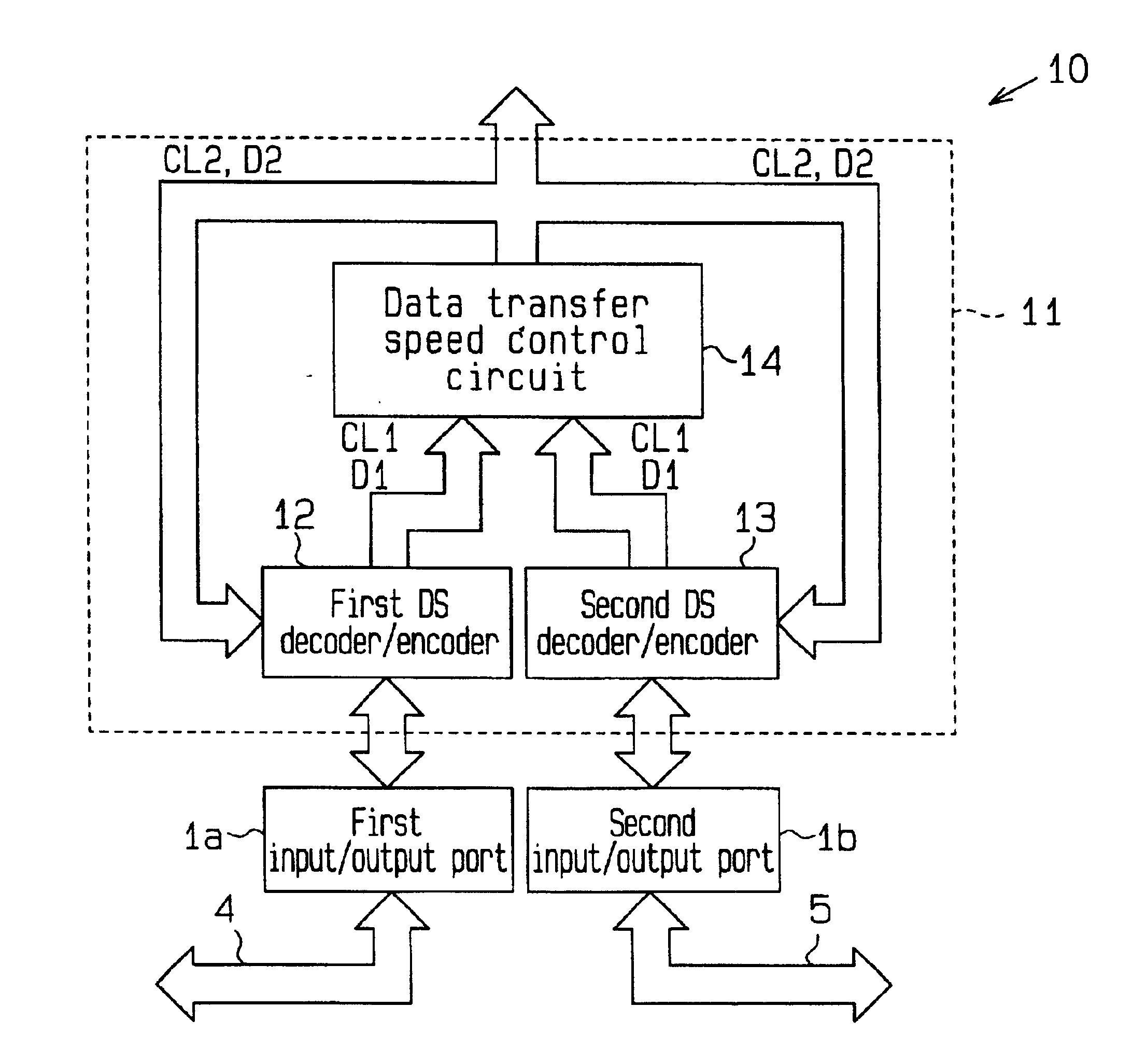
[0026]The interface device 10 of the personal computer 1 is described in FIG. 2. Since the interface devices of th...


PUM


Abstract

A method of determining a transfer speed of an encoded data signal including a clock signal and a data signal is provided. First, the encoded data signal is decoded to generate a decoded clock signal. Then, a data transfer speed of the encoded data signal is determined using the decoded clock signal.

Description

BACKGROUND OF THE INVENTION[0001]The present invention relates to a method of determining a data transfer speed, and more particularly, to a method of determining a data transfer speed in an interface apparatus in conformity to IEEE1394.[0002]The IEEE1394 protocol is known as a standard for an interface for transferring data such as audio data, image data and so on at a high speed between a personal computer and a peripheral device. The IEEE1394 protocol is advantageous in its high degree of freedom in bus topology which permits a daisy chain topology, a star topology, and so on.[0003]A Data-Strobe Link (DS-LINK) coding scheme is employed for a transfer format of the IEEE1394 protocol. The DS-LINK coding scheme encodes a clock signal and a data signal to generate an encoded data signal and a strobe signal. When data having the same value are continuously output, the continuity of the data is represented by changing the value of the strobe signal. A clock signal is generated by perfo...

Claims


Application Information

Patent Timeline
IPC IPC(8): H04L25/02H04L25/40G06F5/12H04L7/00H04L29/08
CPCH04L25/0262G06F5/12
Inventor UENO, HIROTAKA
Owner SOCIONEXT INC
Why Eureka
Try Eureka