
Vacuum breaker with water leak containment device

a vacuum breaker and containment device technology, applied in mechanical equipment, transportation and packaging, functional valve types, etc., can solve the problems of potentially harmful liquid leakage from the valve to the surrounding equipment, and achieve the effect of simple construction

Inactive Publication Date: 2005-06-14
ALLIANCE LAUNDRY SYSTEMS
View PDF11 Cites 11 Cited by
  • Summary
  • Abstract
  • Description
  • Claims
  • Application Information

AI Technical Summary

Benefits of technology

[0004]It is an object of the invention to provide a piston-type vacuum breaker that is relatively simple in construction and adapted for reliable, substantially leak-free operation.
[0008]Still a further object is to provide a vacuum breaker with a liquid capture and containment device of the above kind that is effectively protected from contaminating debris in the outside environment.
[0009]Another object is to provide a relatively simple liquid capture and containment device that is adapted for field retrofitting of conventional vacuum breakers.

Problems solved by technology

The problem arises when a drop in pressure in the line on the supply side of the valve creates a partial vacuum in the supply line tending to draw liquid backwards into the supply line.
When internal pressure within the valve changes rapidly, such as during opening or closing of the valve, pressurized air and liquid within the valve can discharge through the vent opening while the valve piston is in an intermediate position causing undesirable and potentially harmful liquid leakage from the valve to the surrounding equipment.

Method used


Image

  • Vacuum breaker with water leak containment device
  • Vacuum breaker with water leak containment device
  • Vacuum breaker with water leak containment device

Examples


Embodiment Construction

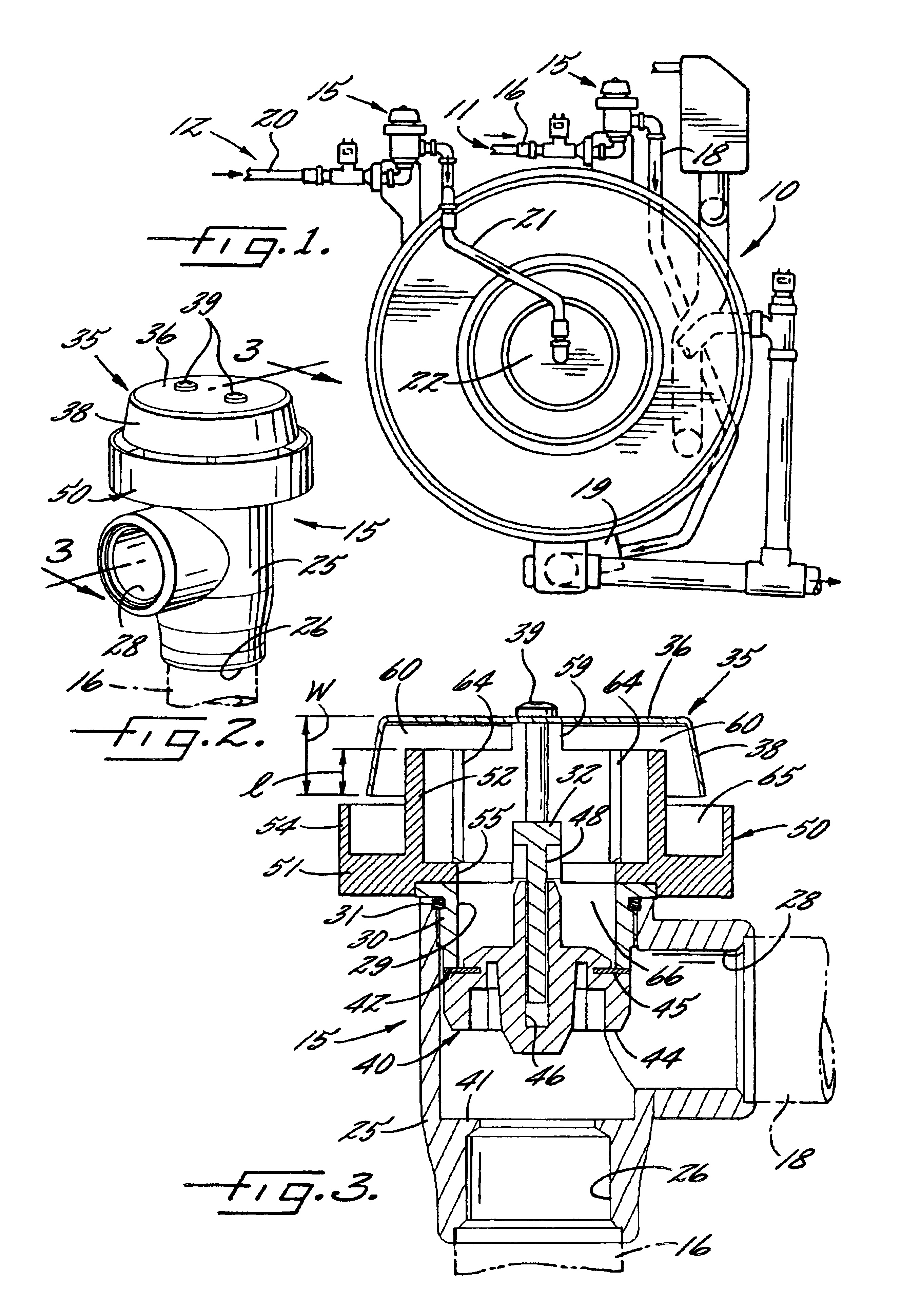
[0026]Referring now more particularly to FIG. 1 of the drawings, there is shown an illustrative commercial laundry machine 10 having liquid supply piping systems 11, 12 each equipped with a vacuum breaker 15 in accordance with the invention. The liquid piping system 11 includes a water supply line 16 which is connected to a liquid inlet of the vacuum breaker 15 and a discharge line 18 connected between the vacuum breaker 15 and a sump 19 on the underside of the washing machine 10 for directing washing water to the machine for use during a washing cycle. The piping system 12 includes a water supply line 20 connected to a liquid inlet of a similar vacuum breaker 15 and a discharge line 21 which connects axially with a front door 22 of the washing machine 10 for directing rinse water during the course of a washing cycle. Since the vacuum breakers 15 are identical in construction, only one need be described in detail.

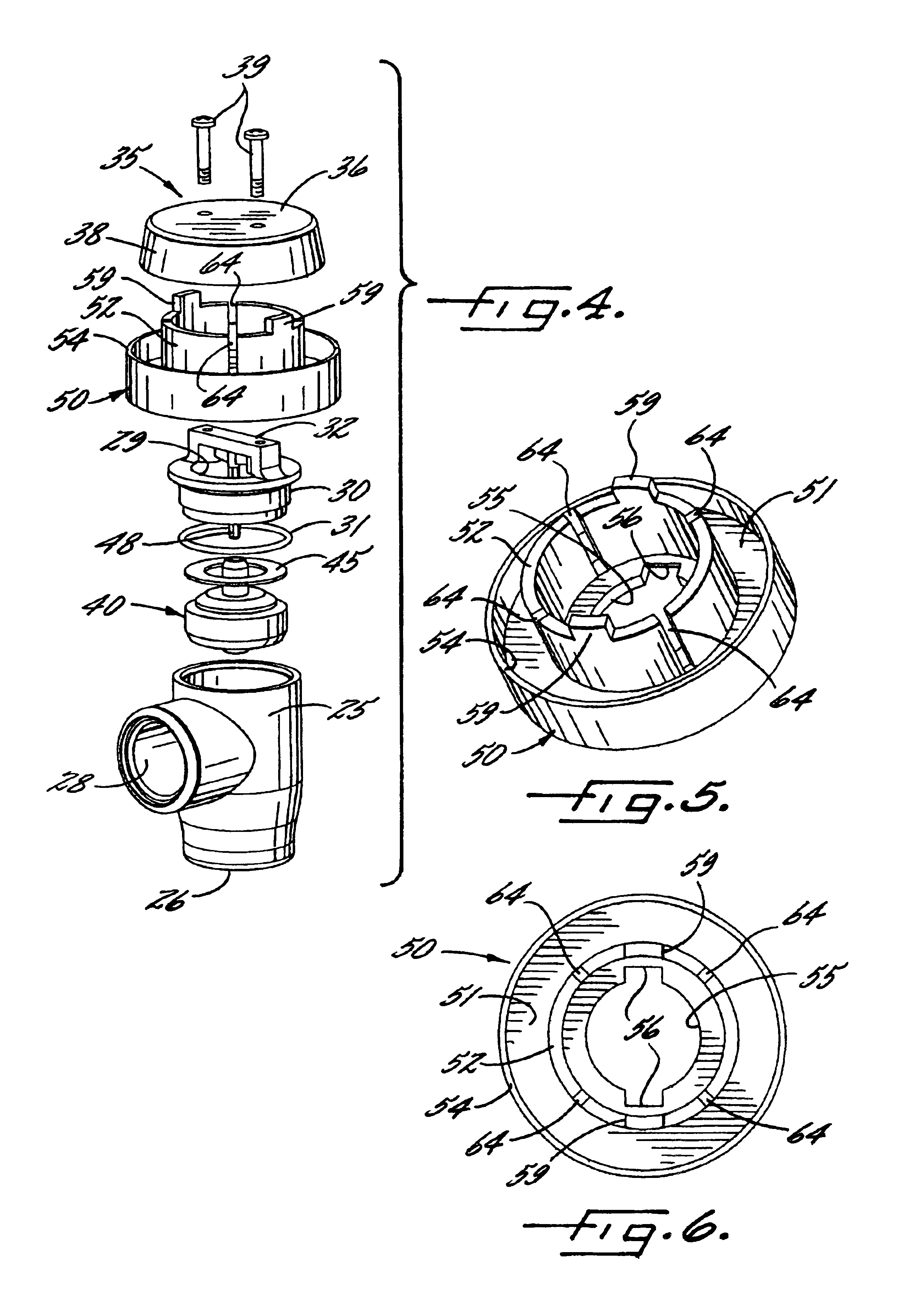
[0027]The illustrated vacuum breaker 15 has a housing 25 which defines...


PUM


Abstract

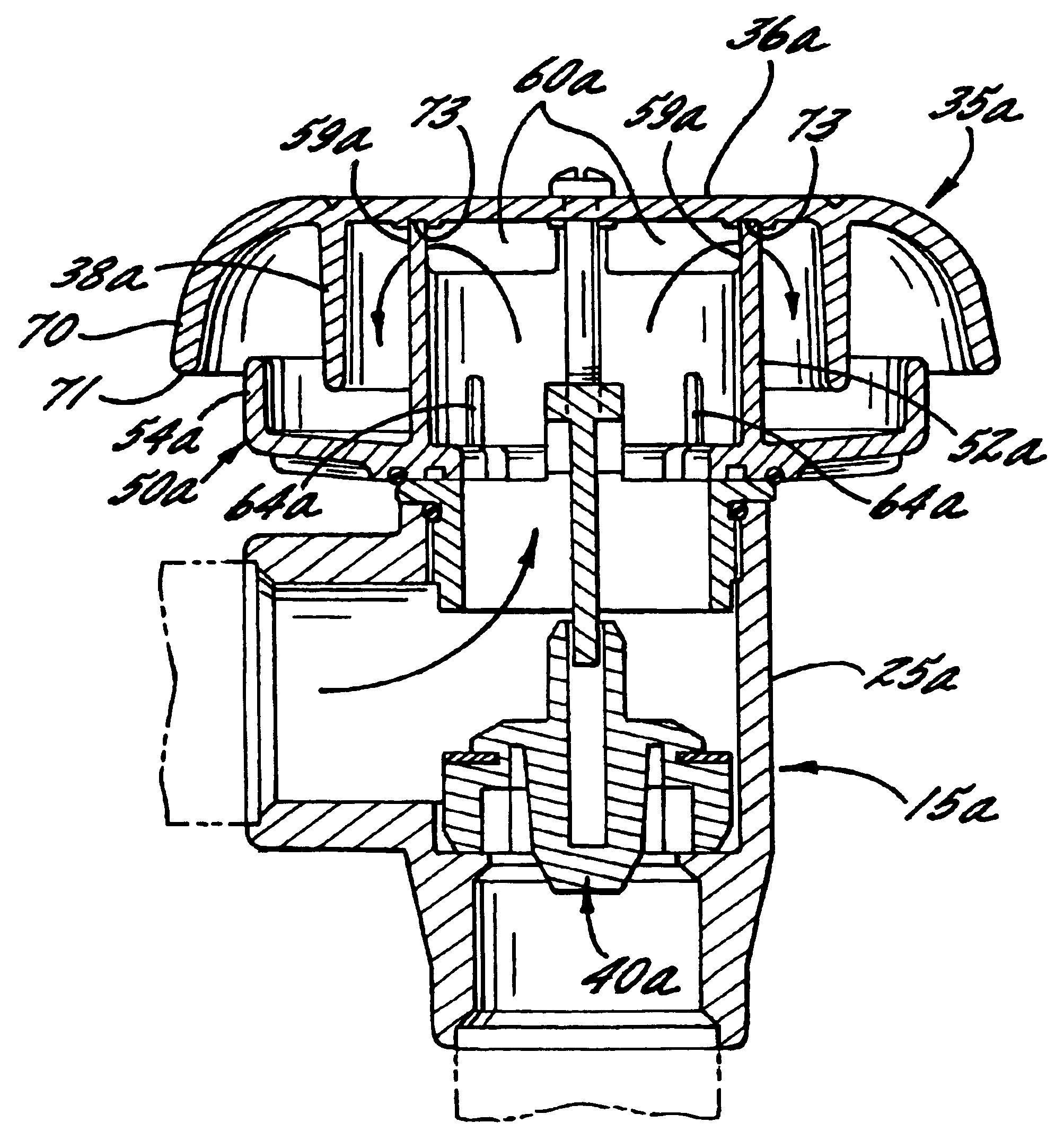
A vacuum breaker having a floating piston that is movable in response to the communication of negative pressure to an inlet port of the vacuum breaker for permitting venting of fluid to the outside atmosphere through a vent opening. The vacuum breaker includes a liquid capture and containment device, which in conjunction with an outer hood, is effective for capturing and containing liquid in a fluid flow stream discharging from the vent opening and redirecting the captured liquid back into the vacuum breaker in order to prevent water leakage.

Description

FIELD OF THE INVENTION[0001]The present invention relates generally to pressure-responsive vacuum breaker valves, and more particularly, to vacuum breaker valves adapted for preventing back flow in liquid supply systems.BACKGROUND OF THE INVENTION[0002]In fluid supply piping systems, it is known to use atmospheric-type vacuum breaker valves to prevent the backward siphoning of water or other liquid, which may be contaminated, from an outlet of the supply line to the supply source. The problem arises when a drop in pressure in the line on the supply side of the valve creates a partial vacuum in the supply line tending to draw liquid backwards into the supply line.[0003]Vacuum breaker valves typically have a vent which is open to atmosphere when pressurized liquid is not supplied to the valve. When pressurized liquid is supplied to the valve, a valve piston moves to a vent closing position, enabling the liquid to be directed into the discharge piping. When internal pressure within the...

Claims


Application Information

Patent Timeline
Patent Type & Authority Patents(United States)
IPC IPC(8): D06F39/08E03C1/10F16K24/06F16K24/00
CPCD06F39/083E03C1/108F16K24/06Y10T137/3294Y10T137/3331
Inventor STEPHENS, ANTHONY
Owner ALLIANCE LAUNDRY SYSTEMS
Learn More