Fiber optic lighting radial arrangement and method for forming the same

a technology of fiber optic strands and radial arrangement, which is applied in the direction of instruments, color-music instruments, rosaries, etc., can solve the problems of limited harrisons, limited apparatus, and inability to illuminate the entire surface area of materials

Inactive Publication Date: 2005-06-14
NOVER BRIAN +1
View PDF42 Cites 9 Cited by
  • Summary
  • Abstract
  • Description
  • Claims
  • Application Information

AI Technical Summary

Benefits of technology

[0059]A forty-third aspect of the present invention is the application of a solar cell or solar array to power the

Problems solved by technology

The apparatus is limited in the requirement of an “illumination sourcing tail section” that separates from the backing material and is gathered into a collector.
Harrison is thus limited in that Harrison utilizes the ends of the fiber optic strands for illumination and does not provide a means to illuminate the entire surface area of the material.
Fuwausa is limited in that the object shape is molded, and pliable plastic and of a shape conducive to evenly illuminating the device.
Each of the above illuminating devices is limited in the ability to freely shape the object.
The more desirable, fiber optic material devices are limited by the inclusion of an illumination sourcing tail section.
The molded objects are limited by the physics to control the emissions within the shape and size of the molded object.
Small objects such as watches, pagers, cell phones, key rings

Method used


Image

  • Fiber optic lighting radial arrangement and method for forming the same
  • Fiber optic lighting radial arrangement and method for forming the same
  • Fiber optic lighting radial arrangement and method for forming the same

Examples


first embodiment

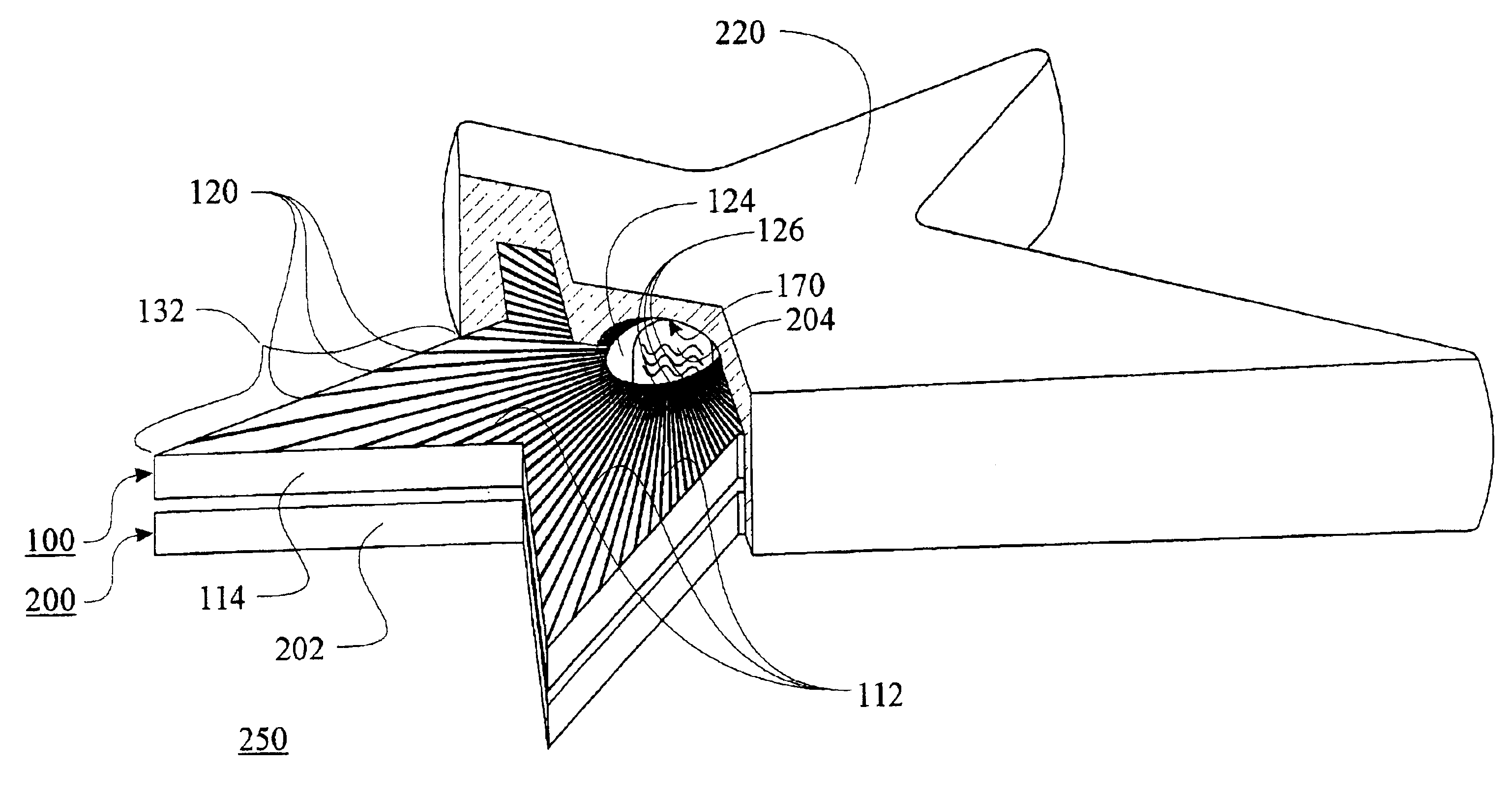
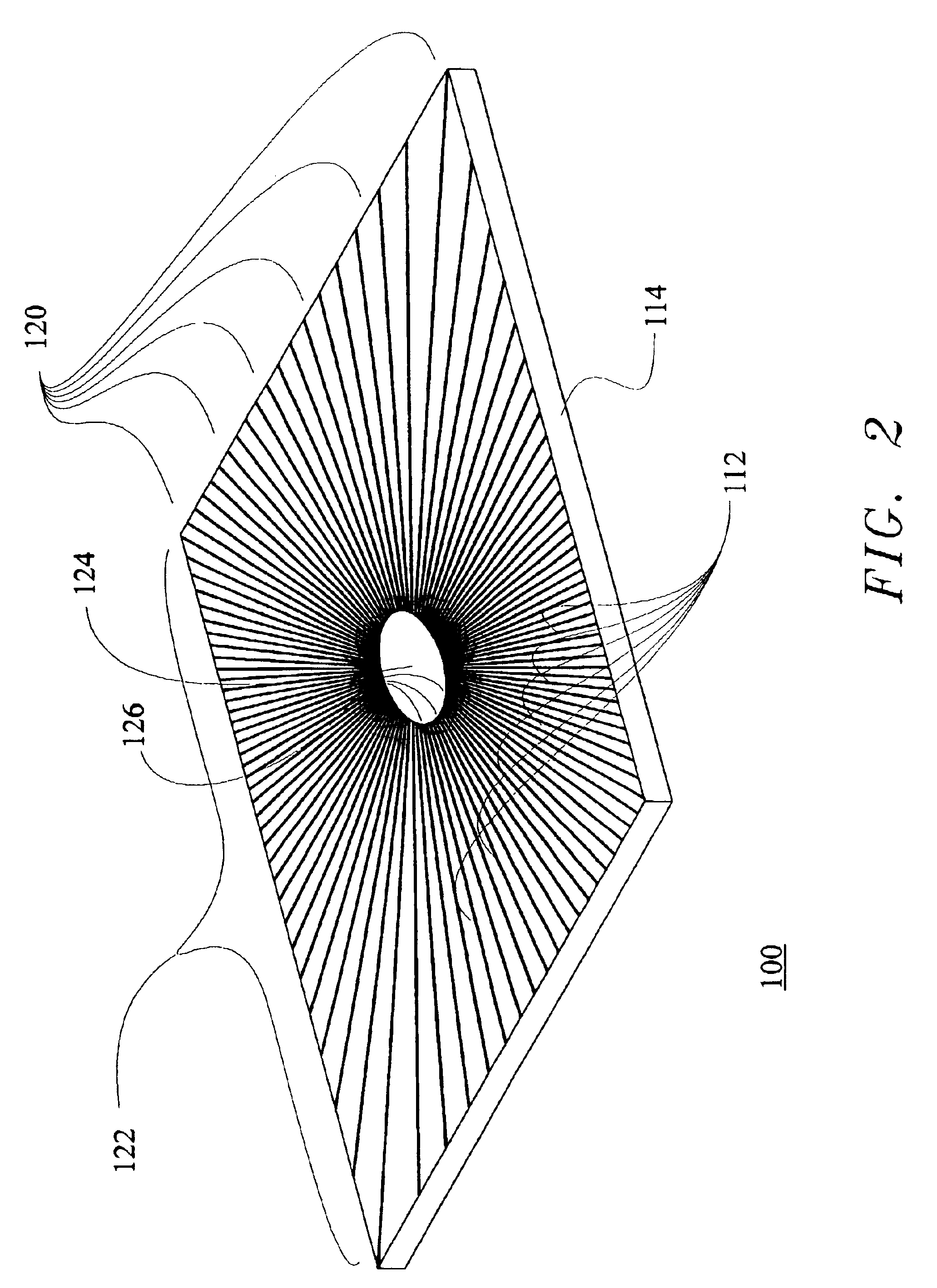
[0072]FIG. 2 is an isometric view of the present invention; a radially arranged fiber optic panel 100 comprising a plurality of radially arranged fiber optic strands 112 positioned radially from at least one centralized illumination receiving position 124. The fiber optic strands 112 can be of any light transmissive fibers such as plastic optical fiber, glass optical fiber, and the like. The plurality of radially arranged fiber optic strands 112 comprise a first end being an illumination receiving port 126 and a second end being an illumination exiting port 120. The plurality of radially arranged fiber optic strands 112 are positioned with the centralized illumination receiving port 126 adjacent the at least one centralized illumination receiving position 124 and the illumination exiting port 120 positioned towards a peripheral edge 122 of a radially arranged fiber optic backing member 114. The plurality of radially arranged fiber optic strands 112 are adhered to said radially arran...

second embodiment

[0073]FIG. 3 is an isometric view of the present invention; an ornamental, radially arranged fiber optic panel 130 comprising a plurality of radially arranged fiber optic strands 112 positioned radially from at least one centralized illumination receiving position 124. The plurality of radially arranged fiber optic strands 112 are positioned with a centralized illumination receiving port 126 adjacent the at least one centralized illumination receiving position 124 and an illumination exiting port 120 positioned towards an ornamentally shaped, peripheral edge 132 of a radially arranged fiber optic backing member 114. The plurality of radially arranged fiber optic strands 112 are adhered to said radially arranged fiber optic backing member 114 and adjacent plurality of radially arranged fiber optic strands 112. The ends of the plurality of fiber optic strands 112 are sheared and polished at the illumination-sourcing end 126 of the plurality of fiber optic strands 112. The illumination...


PUM

PropertyMeasurementUnit
Angleaaaaaaaaaa
Coloraaaaaaaaaa
Perimeteraaaaaaaaaa

Abstract

An apparatus and method of manufacture is disclosed for a fiber optic lighting device. The fiber optic lighting device is formed by adhering fiber optic strands onto a backing material in a radial pattern from a centralized illumination receiving port within a perimeter of the backing material. The centralized illumination receiving port of the fiber optic strands is where the illuminating source would transfer the illuminations into the fiber optic strands. The fiber optic strands can include a surface finish, which enhances the intensity of the light emitting from the fiber optic strands. The fiber optic lighting device can provide a non-linear sheared edge along the entire perimeter of the backing material.

Description

FIELD OF THE INVENTION[0001]The present invention relates to an arrangement of fiber optic strands that employs a radial arrangement, which allows a more compact design and adds the ability to define and permit light to emit from the complete perimeter of the arrangement.BACKGROUND OF THE INVENTION[0002]There are numerous invents utilizing fiber optic lighting as a panel for illuminating an object.[0003]Poly-optical Products commercial distributes a product referred to as Two-layer Uniglo® manufactured under U.S. Pat. Nos. 5,312,569 and 5,499,912. The apparatus comprises a backing member, a plurality of fiber optic strands, the strands are adhered to the backing member in a linear, parallel format, and positioned proximate an adjacent strand to manufacture a ribbon type material. The fiber optic strands separate the backing material and are gathered onto a collector. An illumination source, such as an LED is then coupled to the collector by a coupling device providing a means to con...

Claims


Application Information

Patent Timeline
IPC IPC(8): F21V8/00
CPCG02B6/0006G02B6/0008Y10S362/806
Inventor JACOBS, WILLIAM ALANNOVER, BRIAN N.
Owner NOVER BRIAN
Why Eureka
Try Eureka