
Knee prosthesis with graft ligaments

a knee joint and prosthesis technology, applied in the field of knee joint prosthesis, can solve the problems of general difficulty and reduce the choice of surgeons

Inactive Publication Date: 2005-06-14
BIOMET MFG CORP
View PDF13 Cites 289 Cited by
  • Summary
  • Abstract
  • Description
  • Claims
  • Application Information

AI Technical Summary

Benefits of technology

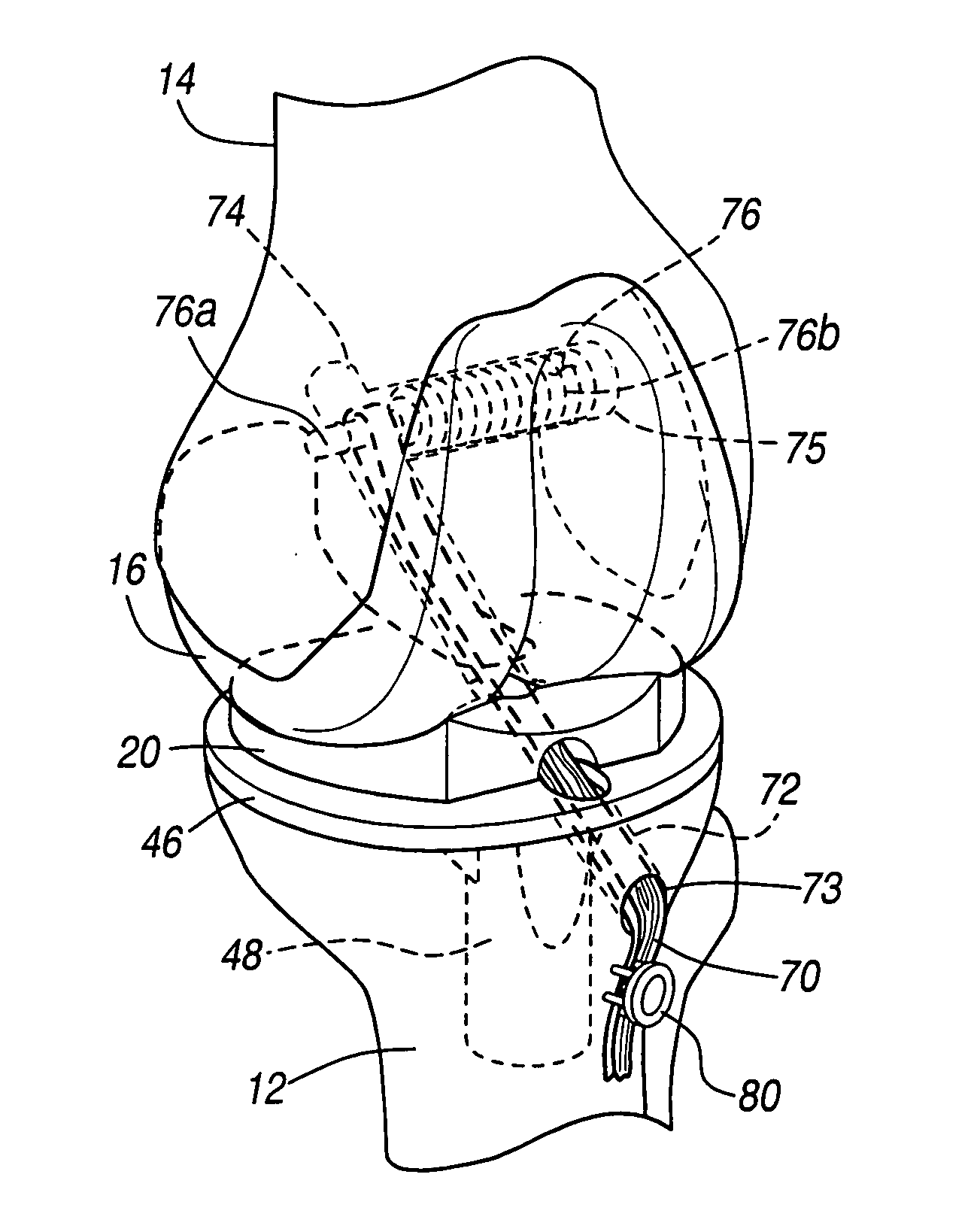
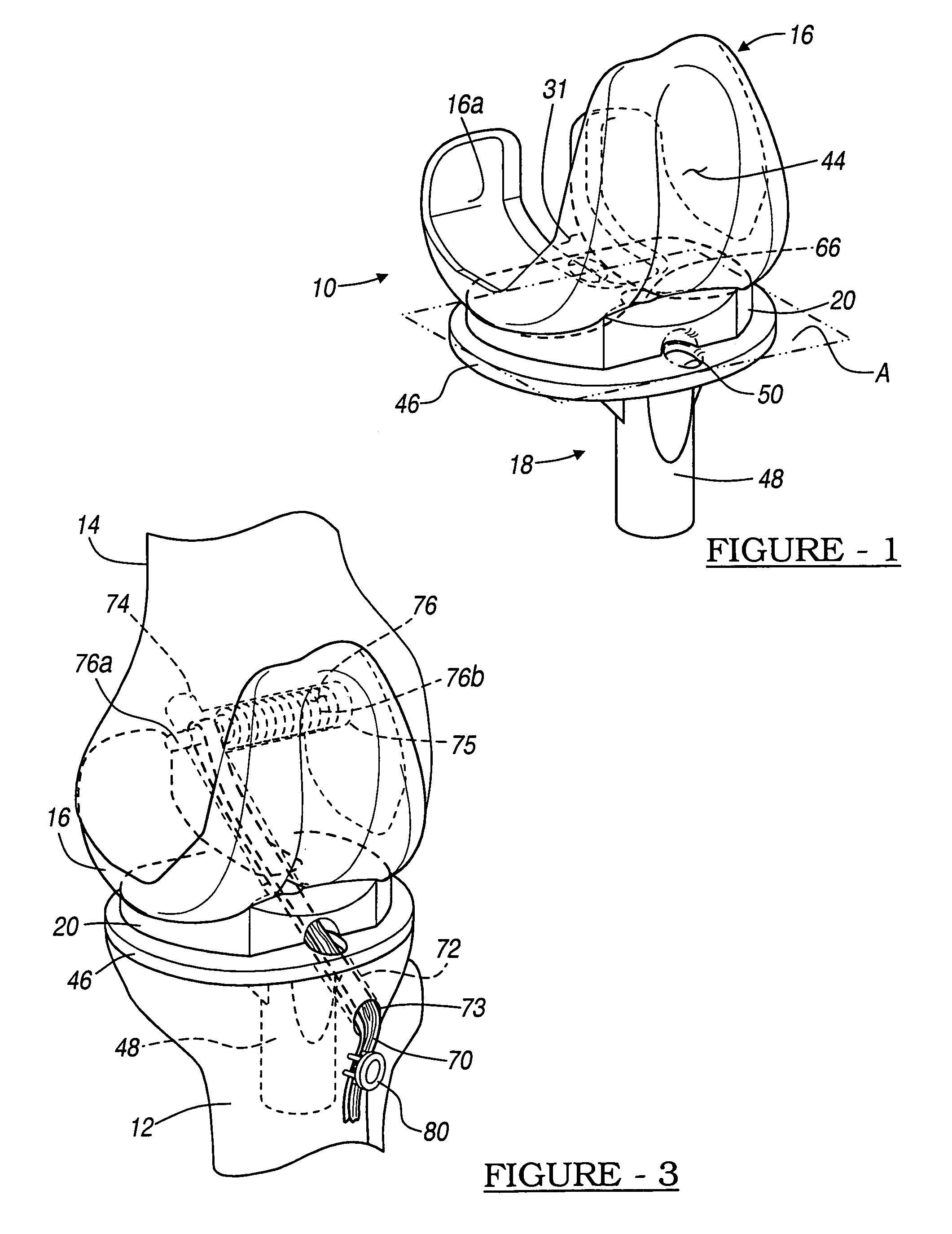
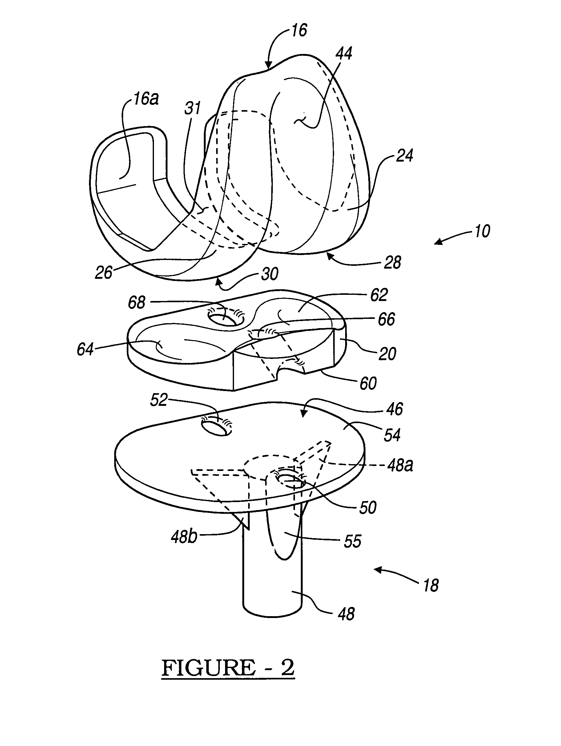
[0010]The knee joint prosthesis allows for a graft for replacing the articulating knee portion of a femur and a tibia. The knee joint prosthesis includes a femoral component, a tibial component, a bearing member, and a graft. The femoral component includes a first femoral bearing surface and a second femoral bearing surface. The tibial component includes a tibial bearing surface. The bearing member includes a first bearing surface which is operable to articulate with the first femoral bearing surface, a second bearing surface which is operable to articulate with the second femoral bearing surface. The bearing may also include a third bearing surface which is operable to articulate with the tibial bearing surface. The graft is coupled to both the tibia and the femur to prevent the knee joint from dislocating and guiding the femoral component along a desired path during extension and flexion.
[0011]The femoral, tibial and bearing components may be precisely placed in the knee during implantation to provide a specific and precise final knee geometry and range of motion. Moreover, precise instrumentation may assist in this placement. Moreover, a single knee replacement surgery may be used to replace the soft tissues and the articulating knee components rather than providing for separate and distinct procedures.
[0012]In one embodiment, a knee joint prosthesis for replacing the articulating portion of a femur and a tibia is disclosed. The knee joint prosthesis includes a femoral component having a femoral bearing surface adapted to be secured to the distal end of the femur and a tibial component having a tibial bearing surface to be secured to the proximal end of the tibia. A bearing member having a first and a second bearing surface is provided to articulate with the femoral bearing surface and the tibial bearing surface. A transplanted biologic ligament connects the femur to the tibia and controls movement of the femur relative to the tibia.
[0013]A second embodiment of the knee joint prosthesis for replacing the articulating portion of a femur and a tibia, wherein a graft is also provided to interconnect the tibia and the femur. A femoral component may be secured to the distal end of the femur where the femoral component includes a first femoral bearing surface and a second femoral bearing surface. A tibial component is included which is adapted to be secured to the proximal end of the tibia where the tibial component includes a tibial bearing surface defining a tibial clearance. A bearing member defines a bearing clearance and includes a first bearing surface operable to articulate with the first femoral bearing surface and a second bearing surface operable to articulate with the second femoral bearing surface. The graft is has a first portion connected to a portion of the femur and a second portion connected to a portion of the tibia. The graft controls movement of the femoral component relative to the tibial component.
[0017]The use of the present invention provides a knee joint prosthesis with a transplanted biologic ligament. The transplanted biologic ligament decreases the friction and wear on the prosthesis and thus provides increased durability and longevity. As a result, a knee prosthetic according to the present invention provides these and other advantages.

Problems solved by technology

Although it is possible to more easily augment or retain the medial and lateral collateral ligaments in the knee and implant a knee prosthesis, this is generally difficult.
It is not known, however, to provide a knee prosthetic, of any of the kinds commonly known, which can also be used with a soft tissue replacement procedure of the anterior cruciate or posterior cruciate ligaments.
This reduces the choices to surgeons.

Method used


Image

  • Knee prosthesis with graft ligaments
  • Knee prosthesis with graft ligaments
  • Knee prosthesis with graft ligaments

Examples


first embodiment

[0040]In the first use of the first embodiment illustrated in FIGS. 1–5, the ACL graft 70 is configured to replicate the function of the biological ACL. In this configuration the ACL graft 70 is connected to the tibia 12 and the femur 14 in a configuration as shown in FIGS. 3–5 and described above. The ACL graft 70 helps prevent posterior subluxation of the femur 14. A second use includes a PCL graft 90 interconnecting the tibia 12 and the femur 14. As the knee joint is moved from extension to flexion, particularly shown in FIGS. 10a–10e, the PCL graft 90 restrains the posterior movement of the tibia 12 with respect to the femur 14 and causes rollback.

[0041]With references to FIG. 6, a third use of the first embodiment of the knee prosthetic 10 is illustrated. The knee prosthetic 10 illustrated in FIG. 6 is substantially identical to the knee prosthetic 10 as described in relation to FIGS. 1–5. Illustrated in FIG. 6, is the knee prosthetic 10 including both the implantation of the A...

second embodiment

[0062]With reference to FIGS. 8 and 9, a knee prosthetic 100 is illustrated where like numerals identify like portions noted above. The knee prosthetic 100 includes a femoral component 102, a bearing 104, and a tibial component 106. The femoral component 102 includes a first condyle 108 and a second condyle 110. The first condyle 108 defines a first femoral bearing surface 112 and the second condyle 110 defines a second femoral bearing surface 114. A femoral clearance 115 is defined between the first condyle 108 and the second condyle 110. A patellar groove 116 is defined between the first condyle 108 and the second condyle 110. The patellar groove 116 may receive either a natural patella or an implant patella.

[0063]The bearing 104 is substantially a floating bearing. The bearing 104 includes a femoral bearing surface 118, which includes a first condyle bearing surface 120 and a second condyle bearing surface 122. The condyle bearing surfaces 120, 122 receive the bearing surfaces 11...

third embodiment

[0078]The knee prosthetic 200 does not allow the same knee kinematics as illustrated in FIGS. 10a–10e. Particularly, rather than replacing the posterior cruciate ligament with a PCL graft 90, a PS post 218 is included in the knee prosthetic 200. Therefore, the motion of the knee, generally created by the PCL, is here simulated with the PS post 218. Nevertheless, the ACL graft 240 has been implanted to replace the resected anterior cruciate ligament. Although the present invention allows for both the ACL and the PCL to be replaced with graft, this may not be possible due to a particular patients anatomy or ailments. Furthermore, it allows the physician a greater flexibility to be able to replace only one ligament while providing a mechanical constraint for other motions of the knee.

[0079]The prosthetics 10, 100, and 200 allow for a choice by a physician of performing a total knee replacement while also performing a reconstruction of the ACL and PCL ligaments. The total knee replacem...


PUM


Abstract

The invention relates to a knee joint prosthesis having a bearing and a biologic ligament for replacing the articulating knee portion of a femur and a tibia. The knee joint prosthesis includes a femoral component, a tibial component, a bearing member, and a biologic ligament. The femoral component includes a first femoral bearing surface and a second femoral bearing surface. The tibial component includes a tibial bearing surface. The bearing member includes a first bearing surface which is operable to articulate with the first femoral bearing surface, a second bearing surface which is operable to articulate with the second femoral bearing surface and a third bearing surface which is operable to articulate with the tibial bearing surface. The biologic ligament is coupled to both the tibia and the femur to prevent the knee joint from dislocating and guiding the femoral component along a desired path during extension and flexion.

Description

TECHNICAL FIELD[0001]This invention relates generally to a knee joint prosthesis which replaces the articulating knee portion of the femur and tibia, and more particularly, to a knee joint prosthesis having a biologically reconstructed ligament.BACKGROUND[0002]Motion of a natural knee is kinematically complex. During a relatively broad range of flexion and extension, the articulating or bearing surfaces of a natural knee experience axial rotation, adduction, abduction, translation in the sagittal plane (rollback and sliding), and translation in the coronal plane. Knee joint prostheses, in combination with ligaments and muscles, attempt to duplicate this natural knee motion, as well as absorb and control forces generated during the range of flexion.[0003]A knee joint prosthesis typically comprises a femoral component and a tibial component. The femoral component and the tibial component are designed to be surgically attached to the distal end of the femur and the proximal end of the ...

Claims


Application Information

Patent Timeline
Patent Type & Authority Patents(United States)
IPC IPC(8): A61F2/08
CPCA61F2/08A61F2/3836
Inventor METZGER, ROBERT
Owner BIOMET MFG CORP
Learn More