Single poly EPROM cell having smaller size and improved data retention compatible with advanced CMOS process

a single-poly eprom and data retention technology, applied in the field of single-poly electricallyprogrammable readonly memory (eprom) cells, can solve the problems of preventing oxide growth, prone cell design to gate oxide leakage, and preventing unwanted leakage through gate oxide of a conventional single-poly eprom cell. , to achieve the effect of prolonging the retention of data and preventing unwanted leakage through gate oxid

Inactive Publication Date: 2005-06-14
NAT SEMICON CORP
View PDF14 Cites 13 Cited by
  • Summary
  • Abstract
  • Description
  • Claims
  • Application Information

AI Technical Summary

Problems solved by technology

Disadvantages of Conventional EPROM Cell
One problem with the conventional single-poly EPROM cell 100 is that this cell design is prone to leakage of gate oxide over the edge of the field oxide.
When a gate oxide is subsequently grown in silicon containing this nitride, oxide growth is impeded and the gate oxide is thinned.
The resulting highly localized thin gate oxide portions can in turn give rise to problems of low-voltage breakdown of the gate oxide, resulting in leakage.
Such gate oxide leakage is particularly problematic in the conventional EPROM cell described above, as the integrity of the voltage stored in the floating gate must remain unaffected over long periods of time.
A second problem of the conventional EPROM cell 100 is the relatively large amount of surface area occupied by the device.
Thus, the amount of silicon surface area consumed by EPROM cell 100 looms as an increasingly serious problem.
The resulting delay between the application of programming voltage and the appearance of sufficient programming bias upon the floating gate posed a serious drawback to these earlier devices.

Method used


Image

  • Single poly EPROM cell having smaller size and improved data retention compatible with advanced CMOS process
  • Single poly EPROM cell having smaller size and improved data retention compatible with advanced CMOS process
  • Single poly EPROM cell having smaller size and improved data retention compatible with advanced CMOS process

Examples


Embodiment Construction

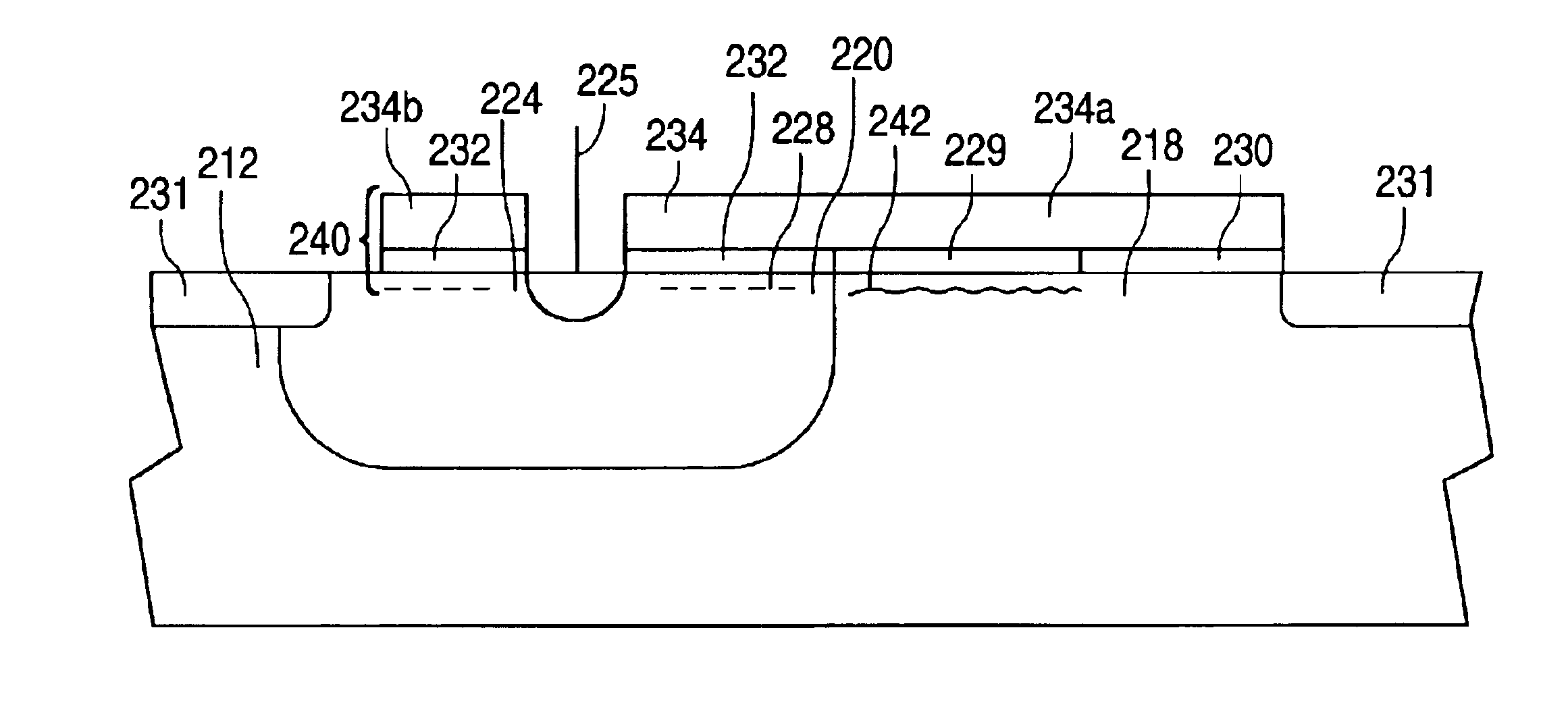
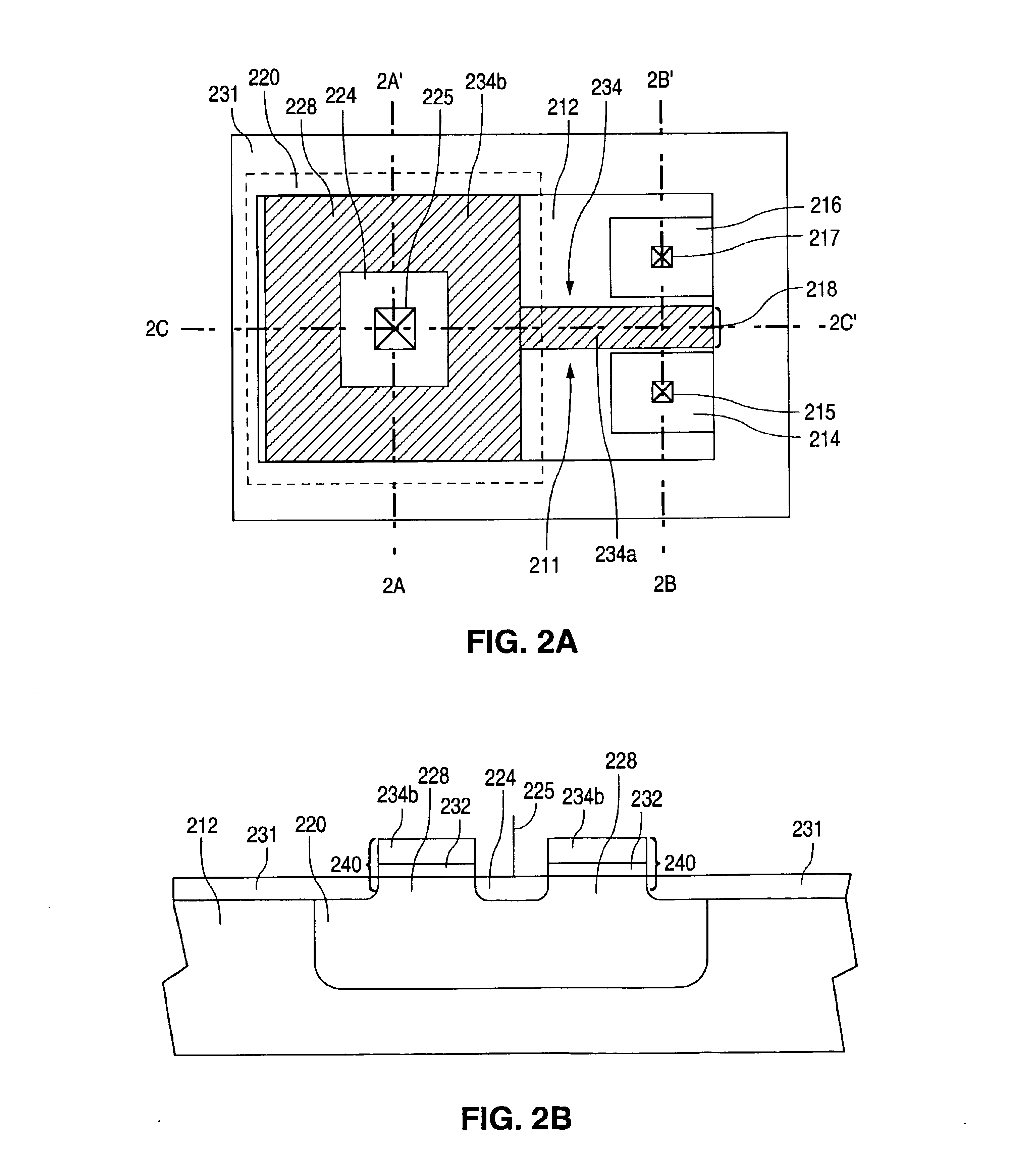
[0047]FIGS. 2A-2D show a series of views that illustrate a single-poly EPROM cell 200 in accordance with a first embodiment of the present invention. FIG. 2A shows a top view of cell 200. FIG. 2B shows a cross-sectional view along line A-A′ of FIG. 2A. FIG. 2C shows a cross-sectional view along line B-B′ of FIG. 2A. FIG. 2D shows a cross-sectional view along line C-C′ of FIG. 2A.

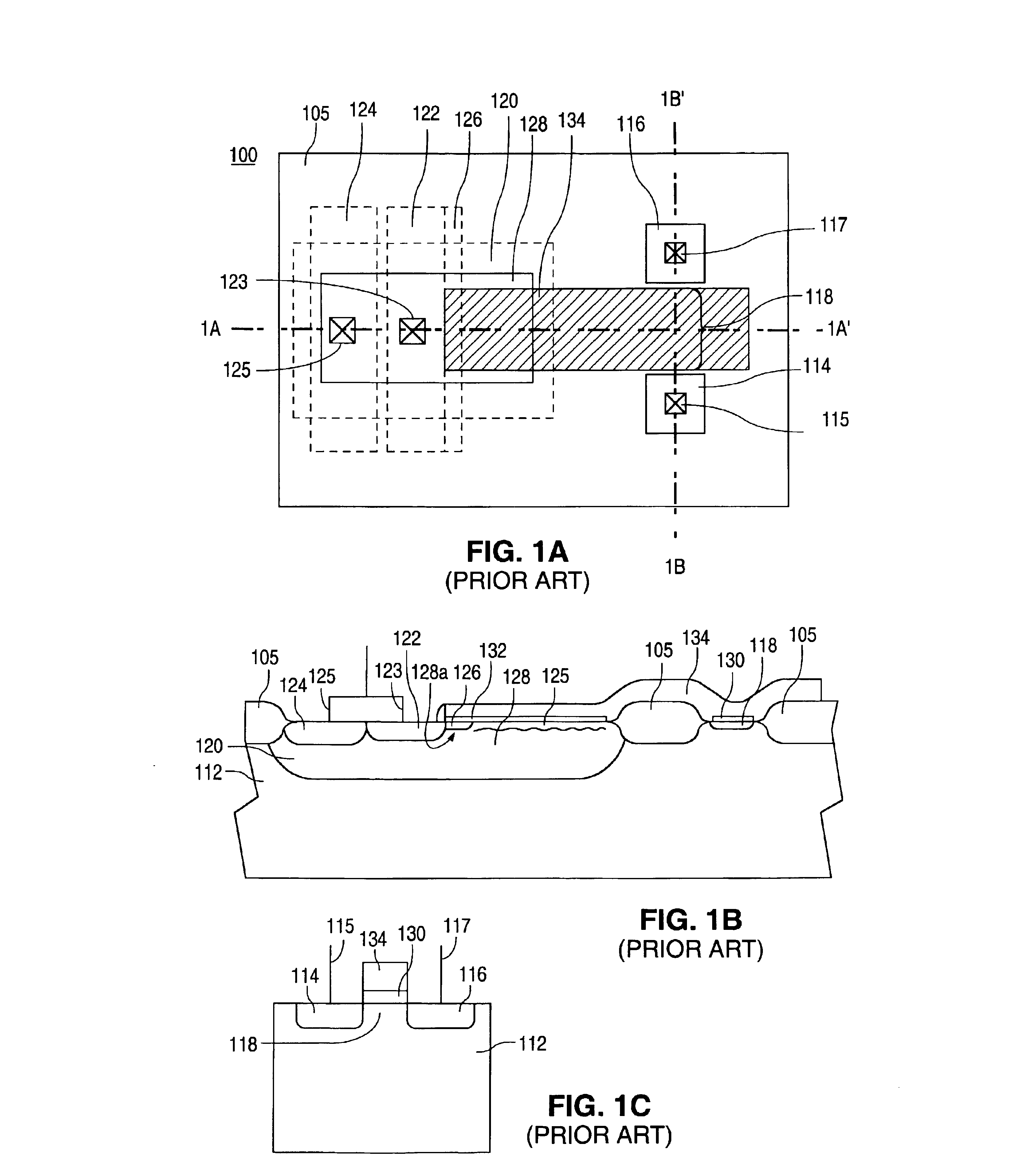
[0048]As shown in FIGS. 2A-2D, EPROM cell 200 is structurally similar to EPROM cell 100 of FIG. 1. Thus, similar reference numerals are utilized to designate structures which are common to both cells.

[0049]As shown in FIGS. 2A-2D, EPROM cell 200 includes spaced-apart source and drain regions 214 and 216 respectively, which are formed in a p-type semiconductor material 212 such as a well or a substrate, and a channel region 218 which is defined between source and drain regions 214 and 216. Source region 214 includes source contact 215. Drain region 216 includes drain contact 217.

[0050]As further shown in FIGS...


PUM


Abstract

Leakage of a single-poly EPROM cell is prevented by eliminating field oxide isolating the source, channel, and drain from the control gate n-well, and by replacing field oxide surrounding the cell with a heavily doped surface isolation region. The EPROM cell also utilizes a floating gate having an open-rectangular floating gate portion over the control gate region, and a narrow floating gate portion over the channel and intervening silicon substrate. The surface area of the open-rectangular floating gate portion ensures a high coupling ratio with the control gate region. The small width of the narrow floating gate portion prevents formation of a sizeable leakage path between the n-well and the source, channel, and drain. To conserve surface area, the EPROM cell also eliminates the p+ contact region and the PLDD region in the control gate well of the conventional EPROM design. This is permitted because the VTp implant step is masked, permitting the control gate region to operate in accumulation mode during application of 5V programming voltages.

Description

PRIORITY CLAIM[0001]The present application is a division of U.S. patent application Ser. No. 09 / 053,199, filed Apr. 1, 1998 now U.S. Pat. No. 6,509,606.BACKGROUND OF THE INVENTION[0002]1. Field of the Invention[0003]The present invention relates to a single-poly electrically-programmable read-only-memory (EPROM) cell and, more particularly, to a single-poly EPROM cell that does not incorporate oxide isolation and thereby avoids problems with leakage along the field oxide edge that can lead to degraded data retention.[0004]2. Description of the Related Art[0005]A single-poly electrically-programmable read-only-memory (EPROM) cell is a non-volatile storage device fabricated using process steps that are fully compatible with conventional single-poly CMOS fabrication process steps. As a result, single-poly EPROM cells are often embedded in CMOS logic and mixed-signal circuits.[0006]FIGS. 1A-1C show a series of views that illustrate a conventional single-poly EPROM cell 100. FIG. 1A sho...

Claims


Application Information

Patent Timeline
Patent Type & Authority Patents(United States)
IPC IPC(8): H01L27/115H01L29/66H01L29/788
CPCH01L29/7883H01L27/115G11C2216/10H10B69/00
Inventor MERRILL, RICHARD B.BERGEMONT, ALBERTCHI, MIN-HWA
Owner NAT SEMICON CORP
Why Eureka
Try Eureka