Electric power steering apparatus

a technology of electric power steering and electric motor, which is applied in the direction of electrical apparatus casings/cabinets/drawers, motor/generator/converter stoppers, dynamo-electric converter control, etc., can solve the problems of increased power loss, increased weight of vehicles, and increased manufacturing costs, so as to reduce the influence of radiation noise, reduce the cost and weight of vehicles, and achieve large output power

Inactive Publication Date: 2005-06-14
MITSUBISHI ELECTRIC CORP
View PDF12 Cites 48 Cited by
  • Summary
  • Abstract
  • Description
  • Claims
  • Application Information

AI Technical Summary

Benefits of technology

[0023]The present invention is intended to solve the above-mentioned variety of problems, and has for its object to provide an electric power steering apparatus which is capable of reducing the influence of radiation noise caused by PWM driving, decreasing the cost and weight thereof and generating large output power.

Problems solved by technology

As a result, there arises a problem that the cost of manufacture becomes high and the weight of the vehicle increases.
In addition, if the length of wiring is extended, there takes place another problem in that a power loss is increased and radiation noise generated due to the PWM operation of the bridge circuit 10 is increased as well.
Also, the increased radiation noise might cause a malfunction of other control equipment, radio noise, etc.

Method used


Image

  • Electric power steering apparatus
  • Electric power steering apparatus
  • Electric power steering apparatus

Examples


embodiment 1

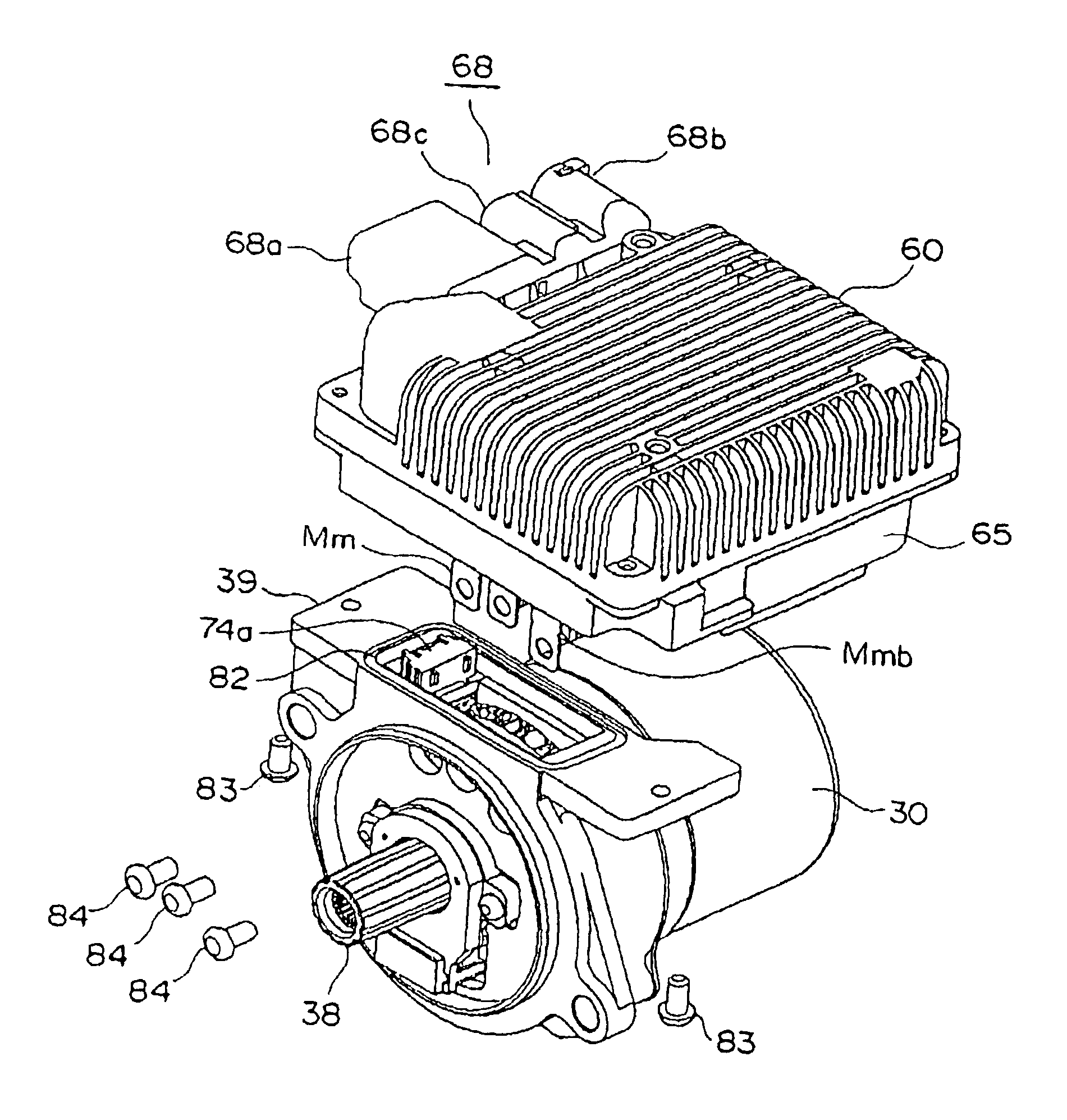
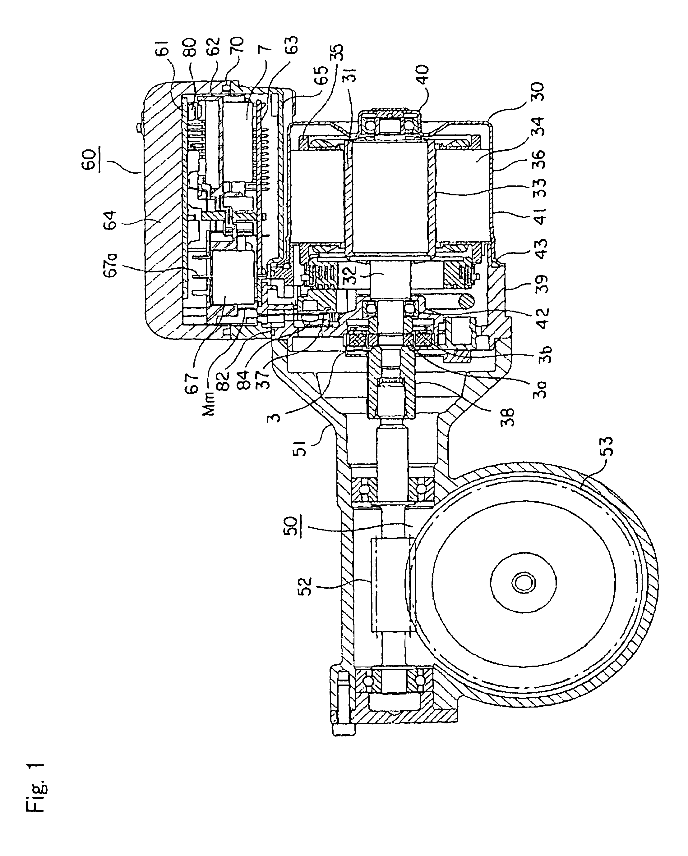
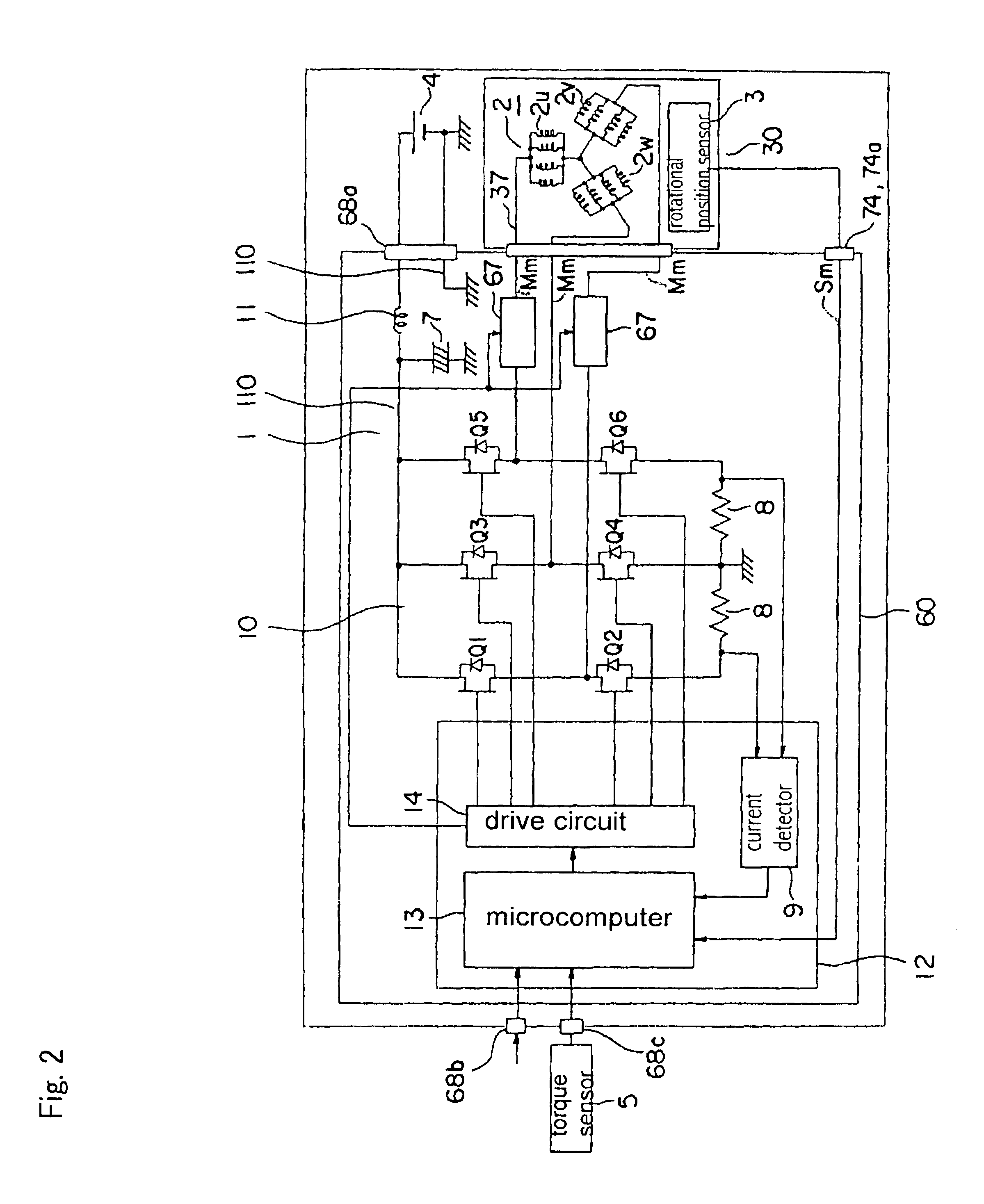
[0042]FIG. 1 is a cross sectional view which shows an electric power steering apparatus according to a first embodiment of the present invention. FIG. 2 is a block diagram of the electric power steering apparatus of FIG. 1. FIG. 3 is an exploded perspective view of the electric power steering apparatus of FIG. 1. FIG. 4 is an exploded perspective view of a control unit 60 of FIG. 1. FIG. 5 is a cross sectional view of the control unit 60 of FIG. 1. FIG. 6 is a plan view of a large current substrate 62 of FIG. 4 when seen from one side thereof. FIG. 7 is a rear view of FIG. 6. FIG. 8 and FIG. 9 are cross sectional views of a part of the control unit 60 of FIG. 1.

[0043]The electric power steering apparatus illustrated includes an electric motor 30 which outputs assist torque to the steering wheel (not shown) of a vehicle, a control unit 60 which controls the operation of the electric motor 30, a battery 4 which supplies current to the electric motor 30 for driving thereof, a torque se...

embodiment 2

[0118]FIG. 11 is a cross sectional view which shows a part of an electric power steering apparatus according to a second embodiment of the present invention.

[0119]In this embodiment, a nut 85 is insert molded to that portion which is electrically connected with the electric motor 30, thereby forming the lid 72.

[0120]The construction of this embodiment other than the above is similar to the construction of the electric power steering apparatus according to the above-mentioned first embodiment.

[0121]In the second embodiment, when the electric motor 30 and the control unit 60 separately assembled are combined into an integral unit, the winding terminals 37 of the electric motor 30, the motor terminals Mm of the control unit 60 and the nut 85 are arranged in this order from the left side in the axial direction of the electric motor 30 in FIG. 11, and they are fixedly coupled with each other by means of the screws 84 to provide mutual electrical connection therebetween.

[0122]In addition,...


PUM


Abstract

An electric power steering removes external wiring connecting between an electric motor and a control unit, whereby the influence of radiation noise caused by a PWM operation can be reduced. In addition, the heat radiation and assemblability of the electric motor and the control unit can be improved, while achieving high power output. A housing 64 with a metal substrate 61 fixedly secured thereto is arranged at a side opposite to an electric motor 30. The cooling fins are formed on an outer side of a housing 64 and on an outer side and an inner side of a cover 65. A metal substrate 61, a large current substrate 62 and a control substrate 63 are arranged inside of the housing 64 and the cover 65 in a laminated structure.

Description

[0001]This application is based on Application No.2002-070240, filed in Japan on Mar. 14, 2002, the contents of which are hereby incorporated by reference.BACKGROUND OF THE INVENTION[0002]1. Field of the Invention[0003]2. Description of the Related Art[0004]In general, in vehicles such as motor cars equipped with an electric power steering apparatus, the steering torque applied to a steering shaft by an operator's steering effort on a steering wheel is detected by a torque sensor so that a control unit can control the current supplied to an electric motor operatively connected with the steering shaft in accordance with the steering torque thus detected, thus causing the electric motor to output a required amount of steering assist torque to the steering shaft through a speed reducer.[0005]FIG. 12 is a block diagram of an electric power steering apparatus which uses a brushless motor as an electric motor.[0006]This electric power steering apparatus includes an electric motor 1 which ...

Claims


Application Information

Patent Timeline
Patent Type & Authority Patents(United States)
IPC IPC(8): B62D5/04H02K11/04H02K7/116
CPCB62D5/0406H02K11/0073H02K7/1166H02K11/33
Inventor TOMINAGA, TSUTOMUFUJIMOTO, TADAYUKI
Owner MITSUBISHI ELECTRIC CORP
Why Eureka
Try Eureka