Zero-voltage switching half-bridge DC-DC converter topology by utilizing the transformer leakage inductance trapped energy

a transformer and inductance trap technology, applied in the direction of dc-dc conversion, power conversion systems, instruments, etc., can solve the problems of increasing component current stresses, voltage stresses and switching losses, and the complexity of the full bridge is an impediment to its wide application, and achieves energy dissipation and electromagnetic interference (“emi”) emissions

Inactive Publication Date: 2005-06-14
ASTEC INT LTD
View PDF17 Cites 30 Cited by
  • Summary
  • Abstract
  • Description
  • Claims
  • Application Information

AI Technical Summary

Problems solved by technology

Increased switching frequency causes increased component current stresses, voltage stresses and switching losses in pulse width modulated (“PWM”) controlled DC—DC converters.
But the complexity of the full bridge is an impediment to its wide application, particularly for lower power levels.
During the off-time period of the two switches of the half-bridge, the oscillation between leakage inductance of the transformer and the junction capacitance results in energy dissipation and electromagnetic interference (“EMI”) emissions.
Hence, the conventional symmetric PWM half-bridge DC—DC converter is not a good candidate for use in DC—DC converters having higher switching frequencies.
The asymmetric duty cycle for the two switches at static states leads to asymmetric voltage and current stresses on components.
Voltage stress on the secondary side rectifier(s) is also uneven, resulting in degradation of the performance of the DC—DC converter unless higher voltage rated components are used.
Moreover, because the power delivered in the two directions in the transformer is uneven, transformer utilization is degraded.
But the uneven power delivery in two transformers and the uneven current stress on the switches still present problems.

Method used


Image

  • Zero-voltage switching half-bridge DC-DC converter topology by utilizing the transformer leakage inductance trapped energy
  • Zero-voltage switching half-bridge DC-DC converter topology by utilizing the transformer leakage inductance trapped energy
  • Zero-voltage switching half-bridge DC-DC converter topology by utilizing the transformer leakage inductance trapped energy

Examples


Embodiment Construction

[0025]The following description of the preferred embodiment(s) is merely exemplary in nature and is in no way intended to limit the invention, its application, or uses.

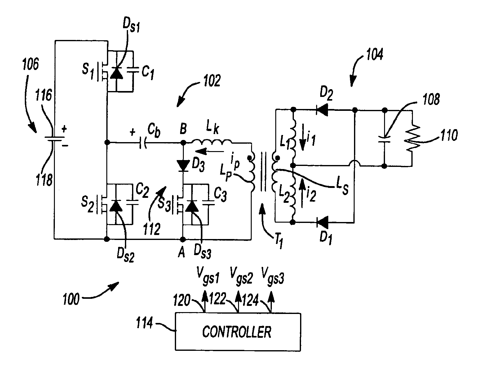
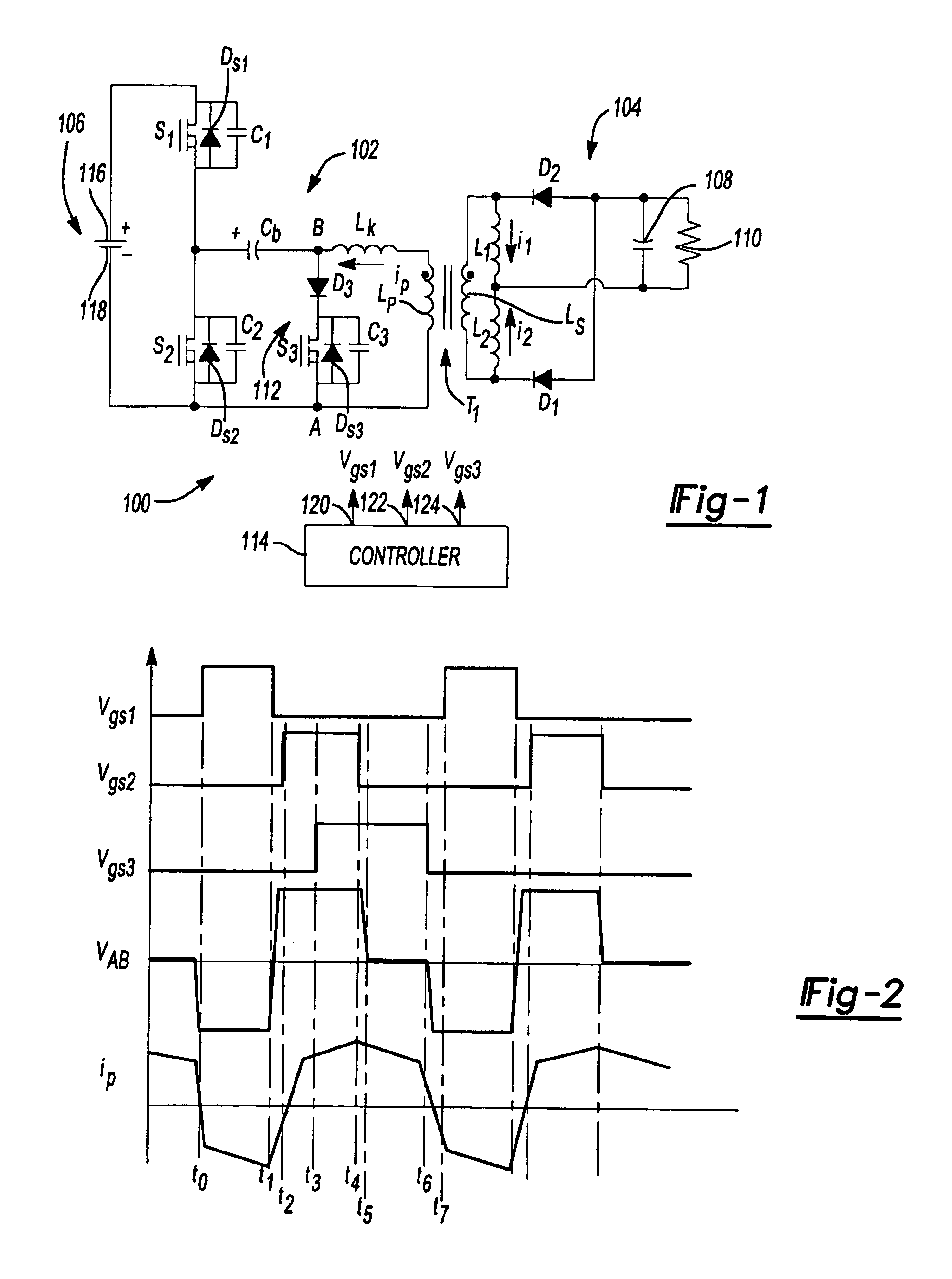
[0026]FIG. 1 shows a circuit topology for a DCS half-bridge ZVS DC—DC converter 100 in accordance with an aspect of the invention. Half-bridge DC—DC converter 100 includes a primary side 102 and a secondary side 104. Primary side 102 includes primary or power switches S1, S2, capacitor Cb and primary windings Lp of a transformer T1. Secondary side 104 of half-bridge DC—DC converter 100 includes secondary windings Ls of transformer T1, first and second inductors L1, L2, diodes D1, D2, filter capacitor 108 and output 110. Half-bridge DC—DC converter 100 also includes an auxiliary branch 112 in primary side 102. Auxiliary branch 112 includes auxiliary switch S3 and diode D3. Half-bridge DC—DC converter 100 also includes a controller 114 having outputs 120, 122, 124 coupled to switches S1, S2, S3. Controller 114 generates...


PUM


Abstract

A duty-cycle-shifted pulse-width modulation controlled half-bridge zero-voltage switching DC—DC converter has a primary side, a secondary side and a transformer coupling the primary side to the secondary side. The primary side has first and second primary switches coupled to a primary winding of the transformer and an auxiliary branch having one side coupled to a junction of the first and second primary switches and a second side coupled to common. The auxiliary branch includes a grounded auxiliary switch that is switched on when one of the first and second primary switches is on to trap leakage inductance energy of the transformer when that primary switch is turned off and thereafter switched off to release the trapped leakage inductance energy to provide a zero voltage switching condition for the other primary switch. The one of the first and second primary switches that is on when the auxiliary switch is switched on may be controlled with duty-cycle-shifted pulse width modulation to provide a zero current switching condition for that primary switch.

Description

FIELD OF THE INVENTION[0001]The present invention relates to DC—DC converters, and more particularly, to high-density, high-frequency, and high efficiency zero-voltage switching (“ZVS”) half-bridge DC—DC converters.BACKGROUND OF THE INVENTION[0002]With the increasing demand for higher power density power conversion and better dynamic performance, the switching frequency in DC—DC converters continues to be increased to reduce the size and cost of passive components. Increased switching frequency causes increased component current stresses, voltage stresses and switching losses in pulse width modulated (“PWM”) controlled DC—DC converters. ZVS DC—DC converters have lower switching loses because of the ZVS, and thus higher efficiency.[0003]Among ZVS DC—DC converters, the phase-shifted ZVS full bridge is attractive because this allows all switches to operate at ZVS by utilizing the leakage inductance of the transformer and the junction capacitance of the MOSFET switches without adding an...

Claims


Application Information

Patent Timeline
Patent Type & Authority Patents(United States)
IPC IPC(8): H02M7/5387H02M3/335H02M3/24
CPCH02M3/33569H02M3/33571
Inventor BATARSEH, ISSAMAO, HONGQAHOUQ, JABER ABU
Owner ASTEC INT LTD
Why Eureka
Try Eureka