
Dynamically spectrally tailored raman pump laser

a raman pump and laser technology, applied in the direction of lasers, semiconductor laser arrangements, semiconductor lasers, etc., can solve the problems of non-optimal solution, scattered, or otherwise lost power transfer to the fiber, and the raman amplifiers have not attracted much commercial interest, so as to facilitate the adjustment of the output power of the emitter and achieve the desired gain

Inactive Publication Date: 2005-06-14
NLIGHT INC
View PDF18 Cites 16 Cited by
  • Summary
  • Abstract
  • Description
  • Claims
  • Application Information

AI Technical Summary

Benefits of technology

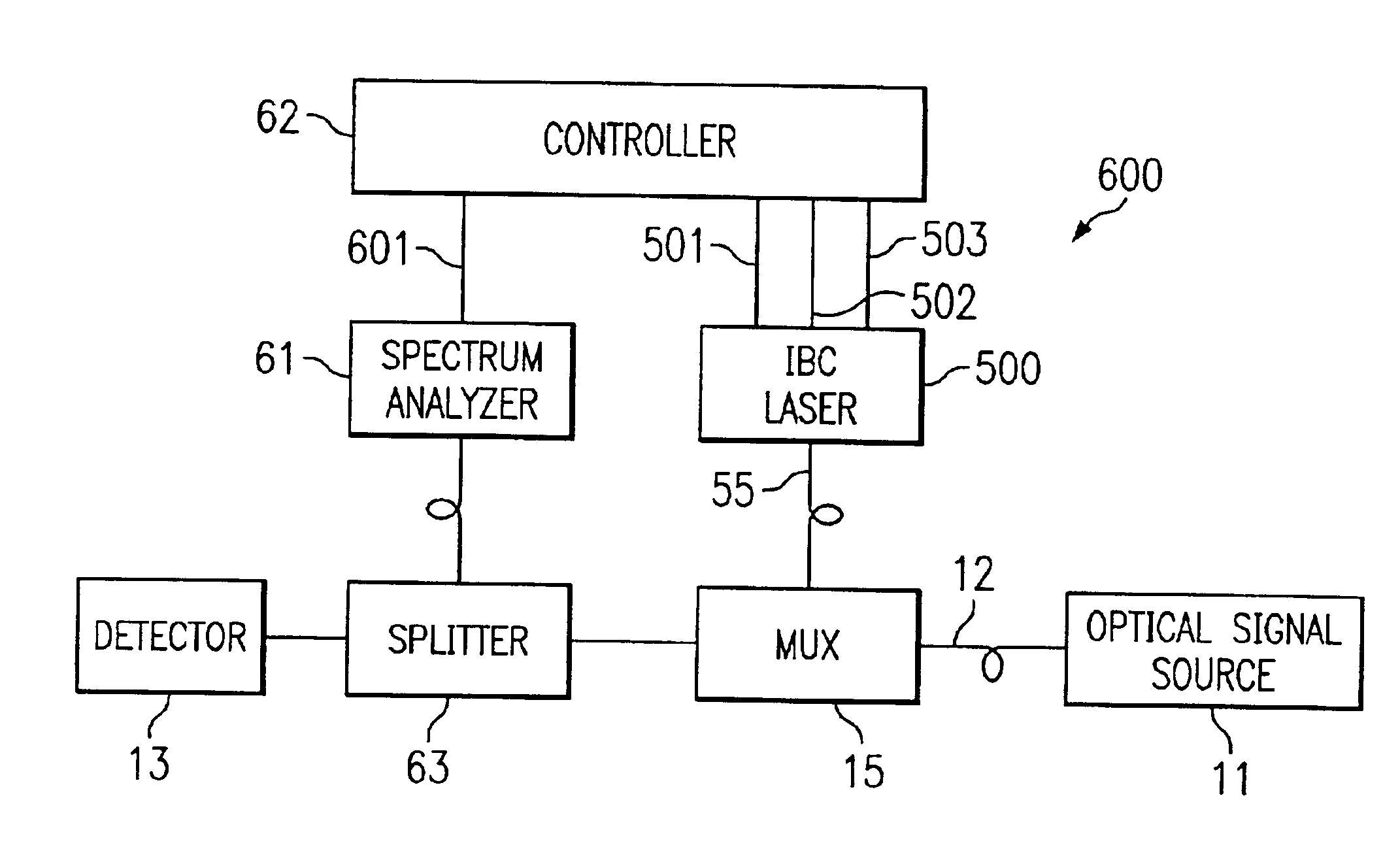
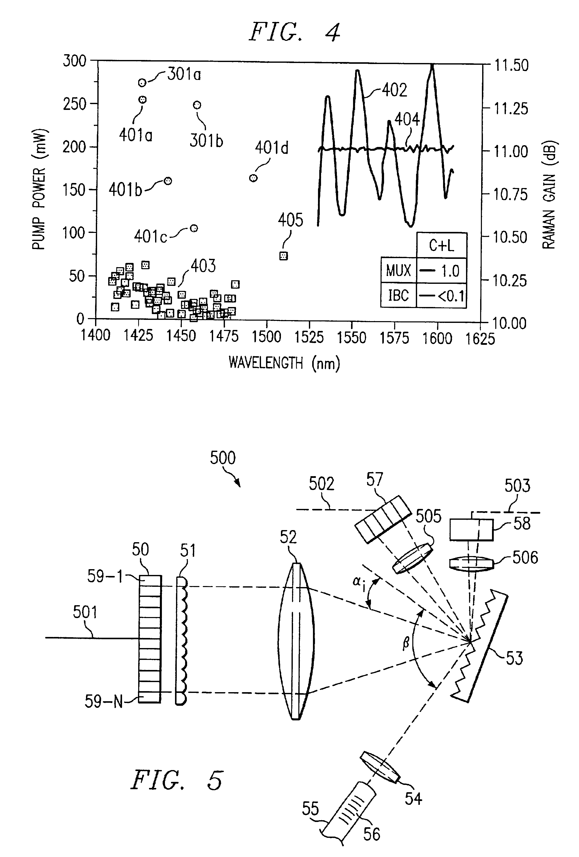
[0009]The present invention is directed to a system and method which provide a Raman pump which is dynamically spectrally tailored in response to feedback from control structure associated with the Raman pump source. In certain embodiments of the present invention, an incoherently beam combined laser (IBC) is utilized to provide a spectrally tailored Raman pump. In these embodiments, emitters in an emitter array are either individually addressable or block addressable to facilitate adjustment of emitter output power of individual emitters of emitter blocks. By adjustment of the output power, the Raman pump is spectrally tailored. An error signal can be generated by measuring the power levels of the optical signal as the optical signal exits the amplifier. The power levels can be compared to a desired power level. By employing suitable control algorithms with this error signal, the desired gain can be maintained dynamically.

Problems solved by technology

As optical signals travel through the optical fibers, a portion of their power is transferred to the fiber, scattered, or otherwise lost.
Until recently, Raman amplifiers have not attracted much commercial interest because significant optical gain requires approximately one watt of optical pump power.
However, this is a non-optimal solution, since this approach adds loss and therefore decreases the signal-to-noise (SNR) ratio of the system.
This becomes an issue when an optical network comprises multiple spans of fiber.
However, this is a non-optimal solution, since this approach increases overall system loss.
This additional loss must be compensated with increased gain which, in turn, increases the ASF noise floor and, hence, decreases the signal-to-noise (SNR) ratio of the system.

Method used


Image

  • Dynamically spectrally tailored raman pump laser
  • Dynamically spectrally tailored raman pump laser
  • Dynamically spectrally tailored raman pump laser

Examples


Embodiment Construction

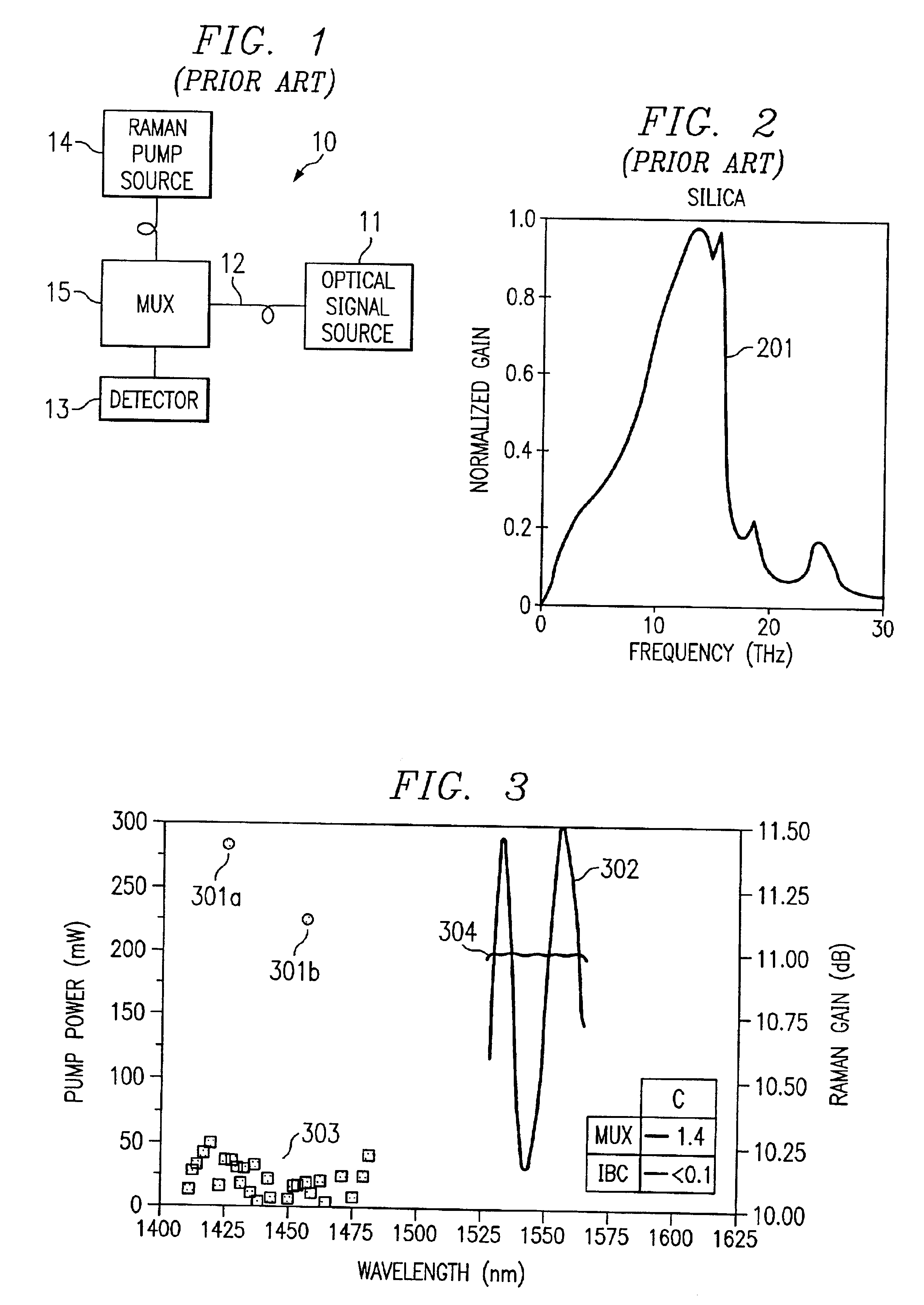
[0022]As discussed in Pump Interactions in 100-nm Bandwidth Raman Amplifier, H. Kidorf et al., IEEE Photonics Technology Letters, Vol. 11, No. 5, May 1999, FIG. 2 depicts Raman gain profile 201 in fused silica. Raman gain profile 201 depicts the gain produced by a spectrally limited source (a pump wavelength of 1 micron). The peak of the Raman gain profile is shifted to the red side of the pump wavelength by the Stokes shift which is approximately 13 THz. This attribute of Raman gain profile 101 causes the Raman process to most strongly amplify wavelengths that are longer than the pump center wavelength.

[0023]It shall be appreciated that a spectrally flat Raman pump will not generate spectrally flat Raman gain. This phenomenon is caused by pump-pump interactions or self-amplification. Self-amplification causes red components (longer wavelengths) of the Raman pump to be amplified by blue components (shorter wavelengths) of the Raman pump. This, in turn, causes greater Raman gain at t...


PUM


Abstract

The present invention is directed to a system and method which provide a Raman pump which is spectrally tailored in response to feedback from control structure associated with the Raman pump source. In certain embodiments of the present inventions, an incoherently beam combined laser (IBC) is utilized to provide a spectrally tailored Raman pump. In these embodiments, emitters in an emitter array are either individually addressable or block addressable to facilitate adjustment of emitter output power. By adjustment of the output power, the Raman pump may be spectrally tailored. The spectral tailoring can occur by employing suitable control algorithms to algorithms to dynamically maintain reasonably flat Raman gain.

Description

CROSS-REFERENCE TO RELATED APPLICATIONS[0001]The application is related to co-pending and commonly assigned U.S. patent application Ser. No. 09 / 945,381, filed Aug. 31, 2001, entitled “SYSTEM AND METHOD FOR PROVIDING A SPECTRALLY TAILORED RAMAN PUMP,” which is incorporated herein by reference.BACKGROUND OF THE INVENTION[0002]At the present time, telecommunication systems are largely based on fiber optic cables. For example, optical networks based on fiber optic cables are currently utilized to transport Internet traffic and traditional telephony information. In such applications, it is frequently necessary to provide an optical signal over significant distances (e.g., hundreds to thousands of kilometers). As optical signals travel through the optical fibers, a portion of their power is transferred to the fiber, scattered, or otherwise lost. Over appreciable distances, the optical signals become significantly attenuated. To address the attenuation, optical signals are amplified. Typic...

Claims


Application Information

Patent Timeline
IPC IPC(8): H01S3/13H01S3/30H01S3/00H01S3/067H01S3/094H01S3/0941H01S5/00H01S5/0683H01S5/14H01S5/40
CPCH01S3/06754H01S5/4062H01S5/0683H01S5/141H01S5/146H01S3/302H01S3/06766H01S3/0677H01S3/094096H01S3/0941H01S5/005H01S5/143
Inventor FARMER, JASON N.
Owner NLIGHT INC
Learn More