Iterative reconstruction methods for multi-slice computed tomography

a computed tomography and reconstruction method technology, applied in tomography, instruments, nuclear engineering, etc., can solve the problems of reducing the scan time, introducing errors, and interpolating helical scanned data into interpolation, so as to prevent warping of image planes, minimize approximation errors, and minimize artifacts near boundary regions

Inactive Publication Date: 2005-06-14
PURDUE RES FOUND INC +2
View PDF1 Cites 75 Cited by
  • Summary
  • Abstract
  • Description
  • Claims
  • Application Information

AI Technical Summary

Benefits of technology

[0018]Another advantage of the present invention is that it uses a CT model in order to match projection data. A CT model minimizes approximation errors and prevents warping of image planes.
[0019]Furthermore, the present invention accounts for boundary conditions, therefore minimizing artifacts near boundary regions of a reconstructed image.
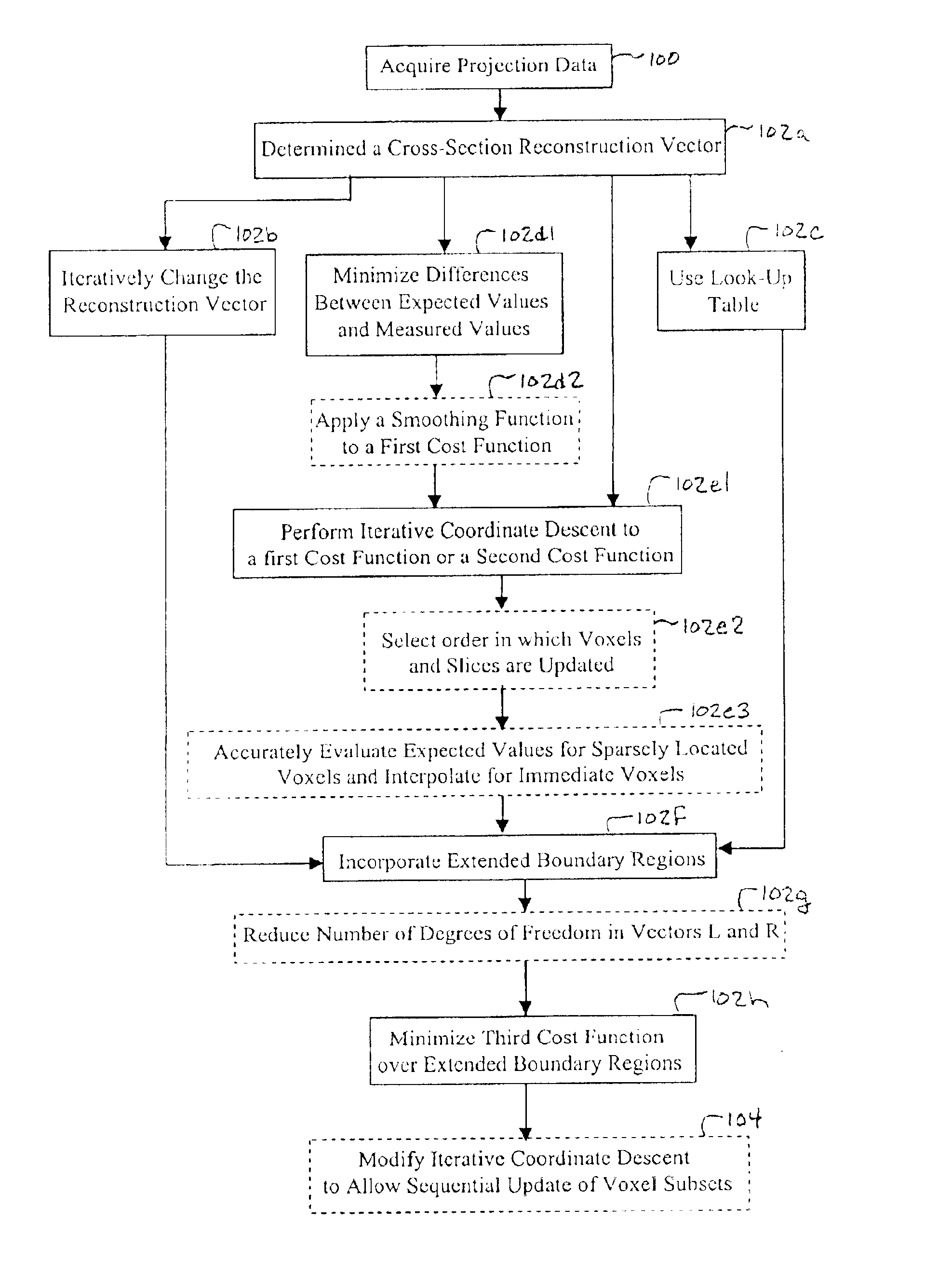
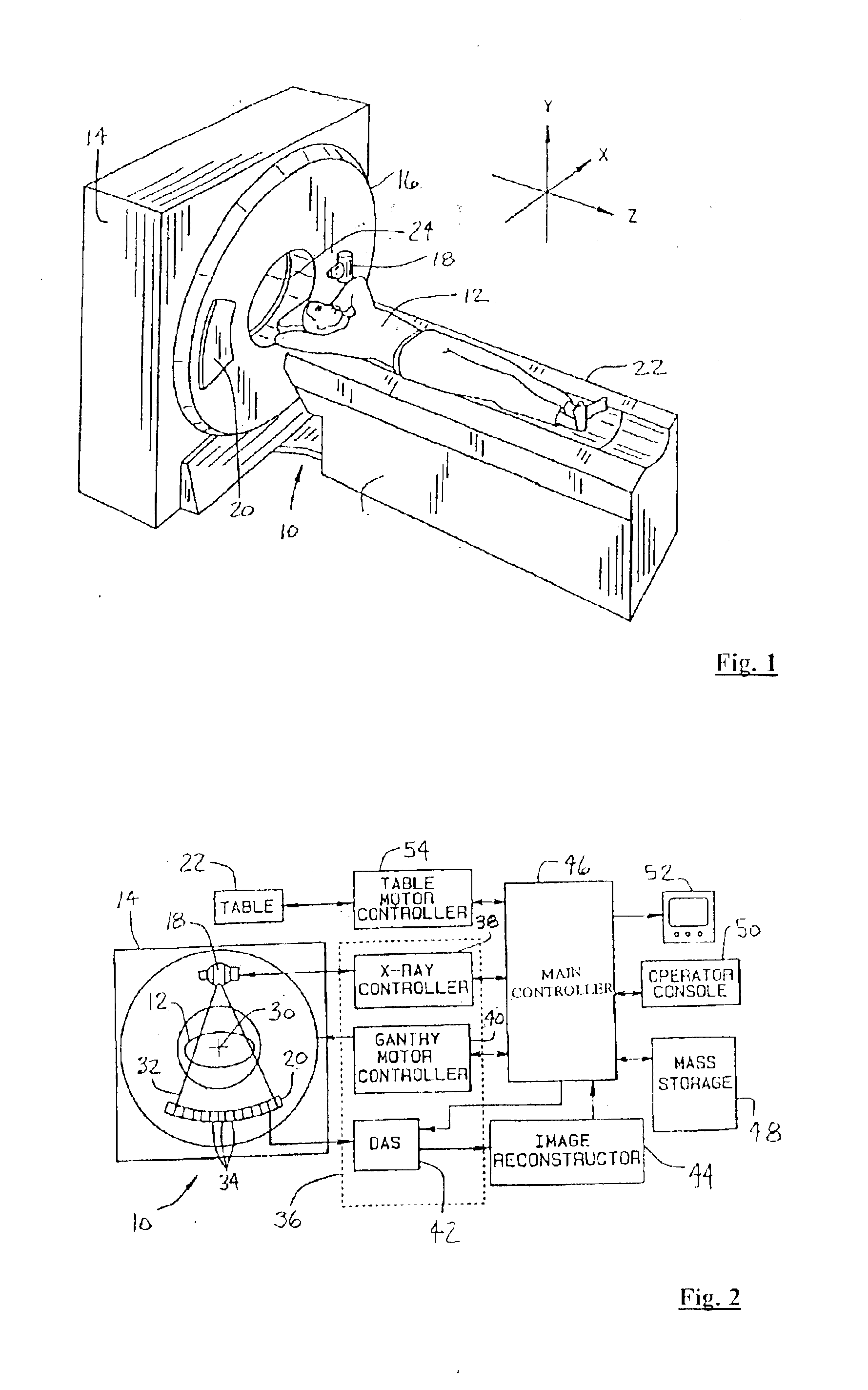
[0020]According to a first broad aspect of the present invention, there is provided an imaging system comprising: a source generating a x-ray beam; a detector array receiving the x-ray beam and generating projection data; a translating table having an object thereon and operable to translate in relation to the source and the detector array; the source and the detector array rotating about the translating table to helically scan the object; an image reconstructor electrically coupled to the detector array and reconstructing an image in response to the projection data using a computed tomography modeled iterative reconstruction technique comprising determining a cross-section reconstruction vector, which approximately matches the projection data via a computed tomography model, wherein the imaging system is a multi-slice computed tomography imaging system.
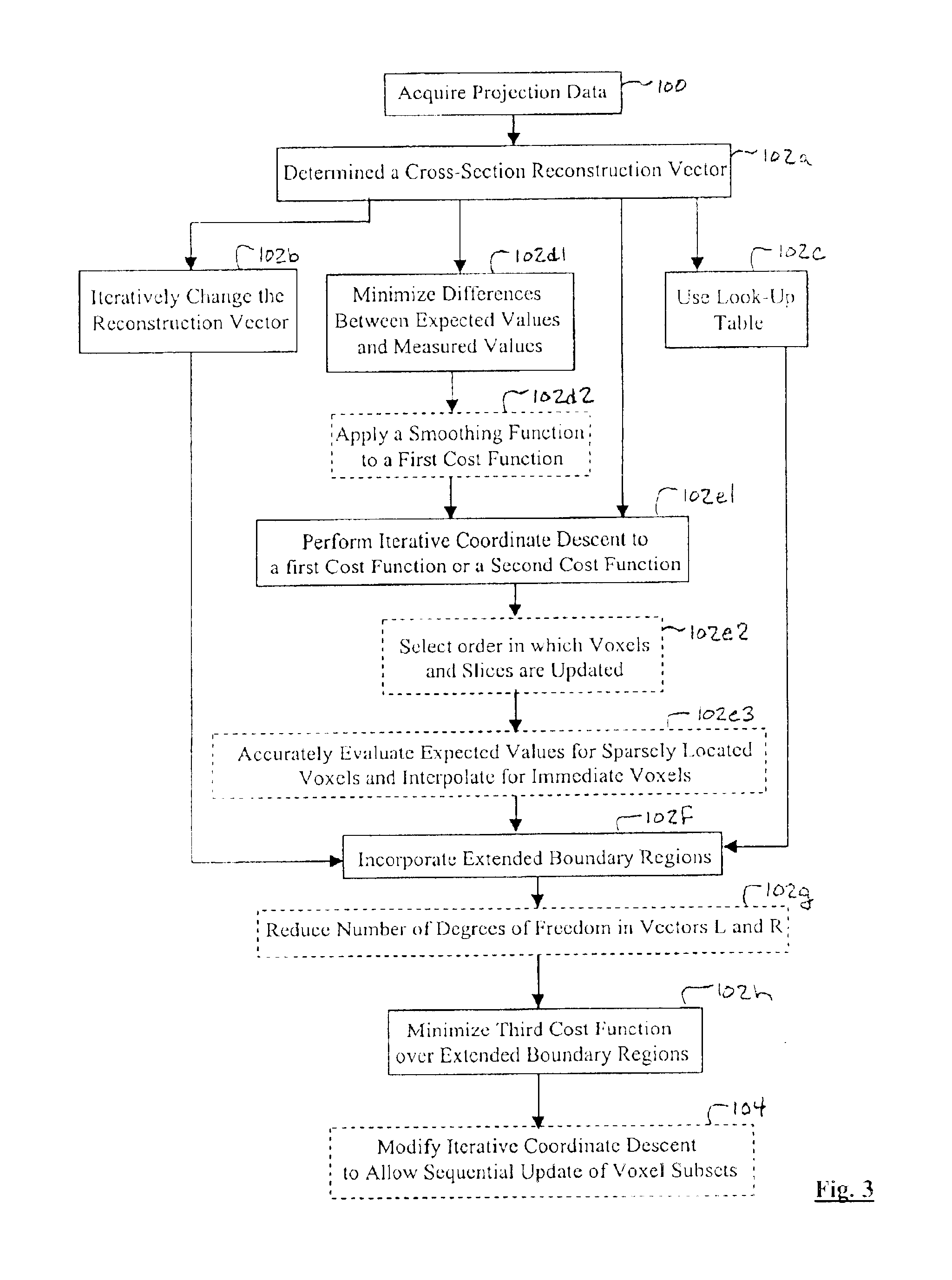
[0021]According to a second broad aspect of the invention, there is provided a method of reconstructing an image of an object for a multi-slice computed tomography imaging system comprising: providing projection data; and performing a computed tomography modeled iterative reconstruction technique to reconstruct the image in response to the projection data comprising determining a cross-section reconstruction vector, which approximately matches the projection data via a computed tomography model.
[0022]According to a third broad aspect of the invention, there is provided a method of reconstructing an image comprising: helically scanning the object to acquire projection data; and performing a computed tomography modeled iterative reconstruction technique to reconstruct the image in response to the projection data comprising; determining a cross-section reconstruction vector, which approximately matches the projection data via a computed tomography model; incorporating extended boundary regions into the computed tomography model; and minimizing a cost function over the extended boundary regions during the iterative reconstruction technique, wherein the image of the object is for a multi-slice computed tomography imaging system.

Problems solved by technology

Unfortunately, conventional helical scan CT has several associated disadvantages.
Acquisition of helical scan data for discrete positions is a limitation in further decreasing scan time.
The interpolation of the helical scanned data introduces errors since the interpolated data does not exactly match true projection values.
The errors result in artifacts in the reconstructed image, particularly near sharp discontinuities.
The interpolation of the multi-slice helical scanned data introduces errors since the interpolated data does not exactly match true measured data.
The errors result in artifacts in the reconstructed image, particularly near sharp discontinuities.
The modifications and warping of the imaging plane causes blurring of the reconstructed image.
The artifacts may therefore obscure important details of the dense objects and sharp discontinuities and may extend radially, obscuring other regions of the reconstruction.
A disadvantage of iterative reconstruction for multi-slice helical scans is that boundary conditions may be difficult to model when the object being scanned extends beyond a scanned range.
Errors in the summation for a particular projection occur when the projection passes through the FOV, but due to the cross plane effect, also passes through regions outside the FOV.
Such projections may result in an erroneous value of a summation computed for a corresponding detector.

Method used


Image

  • Iterative reconstruction methods for multi-slice computed tomography
  • Iterative reconstruction methods for multi-slice computed tomography
  • Iterative reconstruction methods for multi-slice computed tomography

Examples


Embodiment Construction

[0031]It is advantageous to define several terms before describing the invention. It should be appreciated that the following definitions are used throughout this application.

Definitions

[0032]Where the definition of terms departs from the commonly used meaning of the term, applicant intends to utilize the definitions provided below, unless specifically indicated.

[0033]For the purposes of the present invention, the term “image space” refers to a set of vectors arranged in an array for use with a method of the present invention. The array may be of any number of dimensions, such as two-dimensional, three-dimensional, four-dimensional, etc. An example of an image space that may be used in a method of the present invention is a set of all possible images representable on a lattice of a given dimension. A single element (vector) of the set of the image space may be viewed on a visual display apparatus to allow a user to gain information of the interior of a scanned object.

[0034]For the p...


PUM


Abstract

A multi-slice computed tomography imaging system is provided including a source that generates an x-ray beam and a detector array that receives the x-ray beam and generates projection data. A translatable table has an object thereon and is operable to translate in relation to the source and the detector array. The source and the detector array rotate about the translatable table to helically scan the object. An image reconstructor is electrically coupled to the detector array and reconstructs an image in response to the projection data using a computed tomography modeled iterative reconstruction technique. The iterative reconstruction technique includes determining a cross-section reconstruction vector, which approximately matches the projection data via a computed tomography model. Methods for performing the same are also provided including accounting for extended boundary regions.

Description

CROSS-REFERENCE TO RELATED APPLICATIONS[0001]The present invention is related to U.S. patent application Ser. No. 10 / 319,689 entitled “An Iterative Method for Region-of-Interest Reconstruction” filed simultaneously herewith and incorporated by reference herein.BACKGROUND OF THE INVENTION[0002]1. Field of the Invention[0003]The present invention relates generally to multi-slice computed tomography (CT) imaging systems, and more particularly, to an apparatus and methods of reconstructing an image using iterative techniques.[0004]2. Description of the Prior Art[0005]A computed tomography (CT) imaging system typically includes an x-ray source that projects a fan-shaped x-ray beam through an object being imaged, such as a patient, to an array of radiation detectors. The beam is collimated to lie within an X-Y plane, generally referred to as an “imaging plane”. Intensity of radiation from the beam received at the detector array is dependent upon attenuation of the x-ray beam by the object...

Claims


Application Information

Patent Timeline
Patent Type & Authority Patents(United States)
IPC IPC(8): A61B6/03G06T11/00
CPCA61B6/032A61B6/4085A61B6/027G06T11/006Y10S378/901G06T2211/424
Inventor SAUER, KENBOUMAN, CHARLES A.THIBAULT, JEAN-BAPTISTEHSIEH, JIANG
Owner PURDUE RES FOUND INC
Why Eureka
Try Eureka