

Method for microfluidic flow manipulation
a microfluidic and flow device technology, applied in the direction of other chemical processes, process and machine control, instruments, etc., can solve the problems of reagent mixing, excessive mixing channels, and performance limitations,
- Summary
- Abstract
- Description
- Claims
- Application Information
AI Technical Summary
Benefits of technology
Problems solved by technology
Method used
Image

Examples
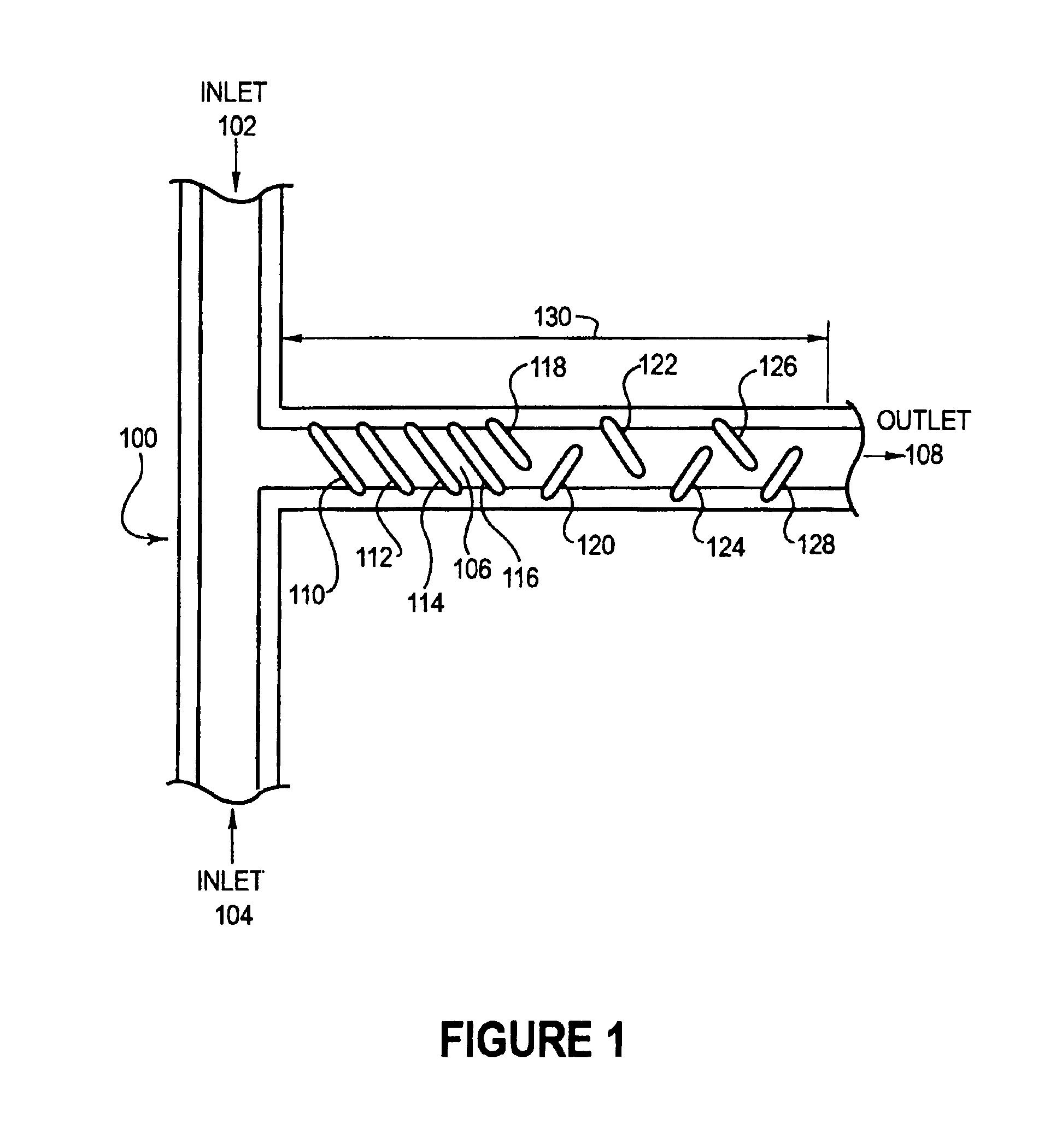
embodiment 100
[0038]FIG. 1 illustrates an embodiment 100 of the present invention of a microfluidic mixer. Two inlet streams 102 and 104 are combined and mixed in the mixing region 106 to produce a mixed flow that exhausts out of the outlet 108. The mixing region 106 comprises several wells 110, 112, 114, 116, 118, 120, 122, 124, 126, and 128 that are recessed into the outlet 108.
first embodiment
[0039]In a first embodiment, the channels have a uniform, trapezoidal cross section, with the width at the top being 72 μm, depth 31 μm, and the width at the bottom being 28 μm. The wells 110, 112, 114, 116, 118, 120, 122, 124, 126, and 128 have a depth of 85 μm in the center of the well.
[0040]The wells 110, 112, 114, and 116 are parallel to each other and uniform in size. The wells are angled approximately 45 degrees from the axis of the outlet 108. The wells 118, 120, 122, 124, 126, and128 are perpendicular to each other and are approximately 45 degrees from the axis of the outlet 108.
[0041]The flow of reagents through the embodiment 100 may be electrokinetic, electroosmotic, or pressure driven flow. Since the electroosmotic flow is a wall driven phenomenon based on the surface charge of the microchannel wall and on the local electric field, the fluid may enter and follow the contour of the wells, with the slanted well design used to induce lateral transport across the channel. In...
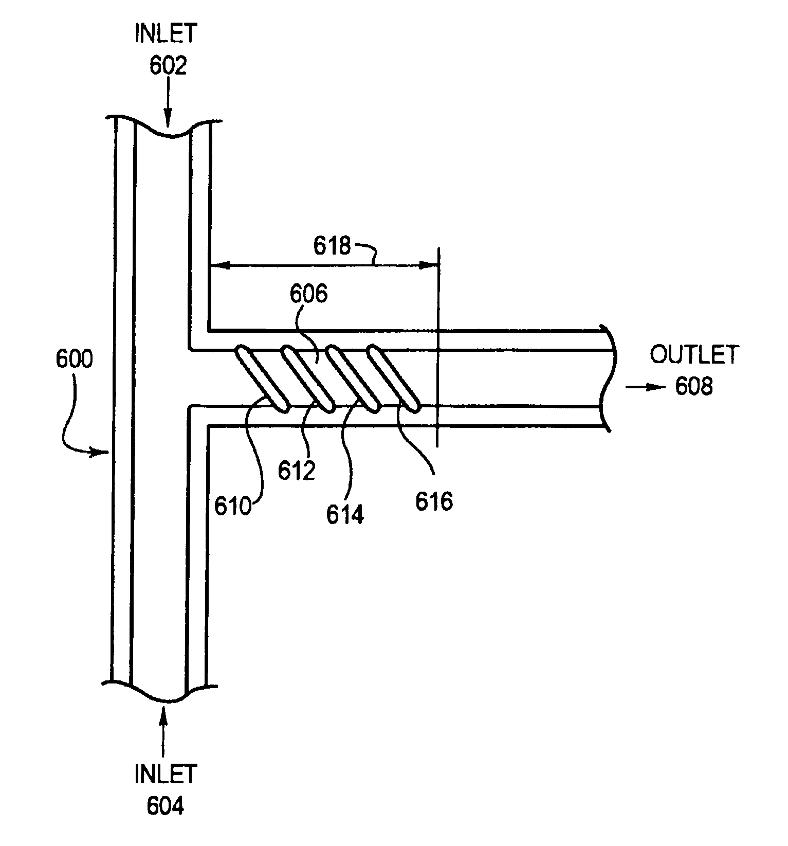
embodiment 600
[0051]FIG. 7 is a white light microscopy image of an example of embodiment 600.
[0052]FIG. 8 is a graph that illustrates the degree of mixing of two reagents using embodiment 600 and an embodiment similar to embodiment 600 but with three wells instead of four. The experimental results of FIG. 8 show results for electroosmotic flow of 0.06 cm / s taken 183 μm from the point of confluence of the inlet flows. The horizontal axis is the position across the width of the outlet stream 608 and the vertical axis is the normalized intensity of Rhodamine B. The same experimental setup was used for the results of FIG. 3 as FIG. 8, with the differences being the configuration of the mixing region and the position of the measurements.
[0053]The curve 802 represents the mixing profile of the two inlet streams when no mixing wells are present. The curve 804 represents the perfect mixing of the two streams. The curve 806 represents the mixing profile for the electroosmotic flowrate of 0.06 cm / s and a t...
PUM
 Abstract
Description
Claims
Application Information