Method of controlling a channel between a radio terminal and a cellular radiocommunication infrastructure, and access network implementing such a method

a radio terminal and radiocommunication infrastructure technology, applied in the field of radiocommunications, can solve the problems of not providing the most significant bits (hfn), not optimal, and using csn counters, so as to reduce the risk of obsolescence of adjustment data transmitted through the core network, reduce the duration of transmission, and simplify the procedure

Inactive Publication Date: 2005-06-21
ALCATEL LUCENT SAS
View PDF4 Cites 60 Cited by
  • Summary
  • Abstract
  • Description
  • Claims
  • Application Information

AI Technical Summary

Benefits of technology

[0058]To simplify the procedure, the relocation phase will generally be performed after a phase of suppressing each first path not passing through the second controller.
[0059]When there is a macrodiversity phase, the adjustment data are advantageously transmitted from the first controller to the second controller through an interface provided between the radio network controllers, without passing through the core network. This avoids the need for the messages transporting the offset data to have to be processed by the switches of the core network, thereby minimizing the duration of transmission of the adjustment data and hence the risk of them arriving late at the second controller.
[0060]Alternatively, ...

Problems solved by technology

This situation is encountered in particular when a DPCH is not sufficient to provide the transmission bit rate required by the application.
However, this is not optimal since it is possible to dispense with the exchanges occurring on the Iur interface and to free the previous SRNC, by contriving matters so that the DRNC becomes the new SRNC for the communication in progress.
A problem posed by this is the transferring of the CSN counter employed by the ciphering algorithm in the transparent RLC mode.
However, this does not provide the most significant bits (HFN).
These arrangements do not solve the aforesaid problem since between the moment at which the SRNC transmits the value of HFN and that at which the DRNC receives it, the HFN in force on the UE side has been able to be incremented.
This occurs each time the HFN takes more than 2.56 s to be received by the...

Method used


Image

  • Method of controlling a channel between a radio terminal and a cellular radiocommunication infrastructure, and access network implementing such a method
  • Method of controlling a channel between a radio terminal and a cellular radiocommunication infrastructure, and access network implementing such a method
  • Method of controlling a channel between a radio terminal and a cellular radiocommunication infrastructure, and access network implementing such a method

Examples


Embodiment Construction

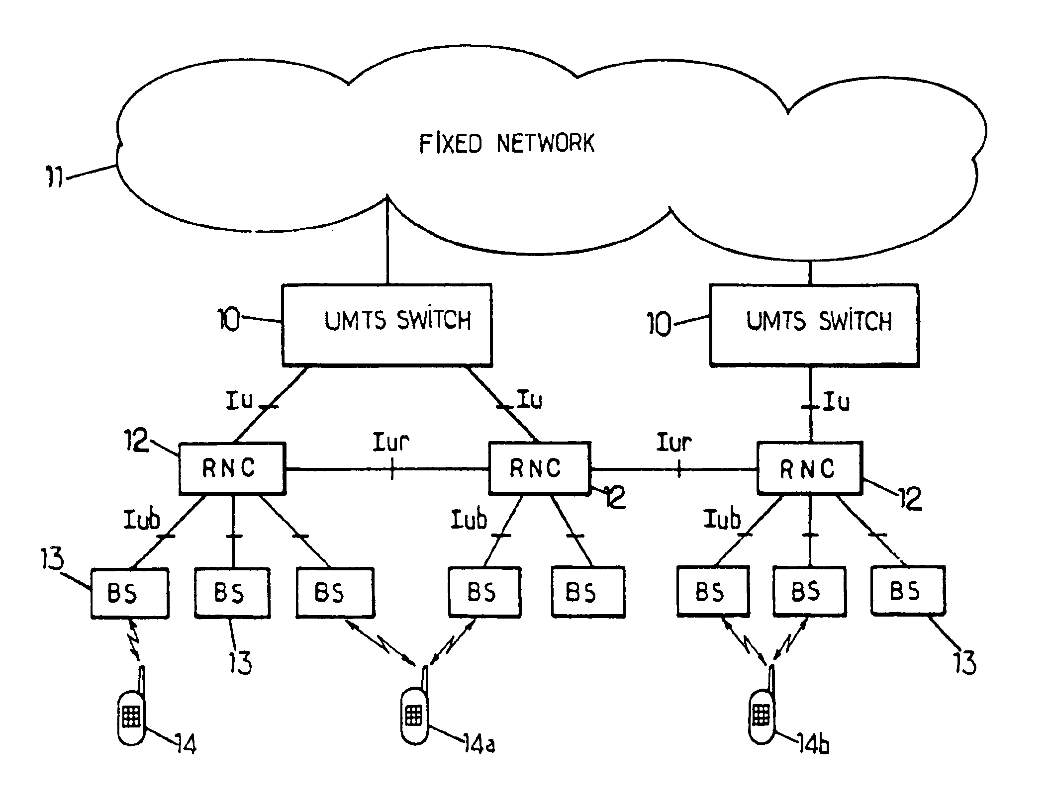
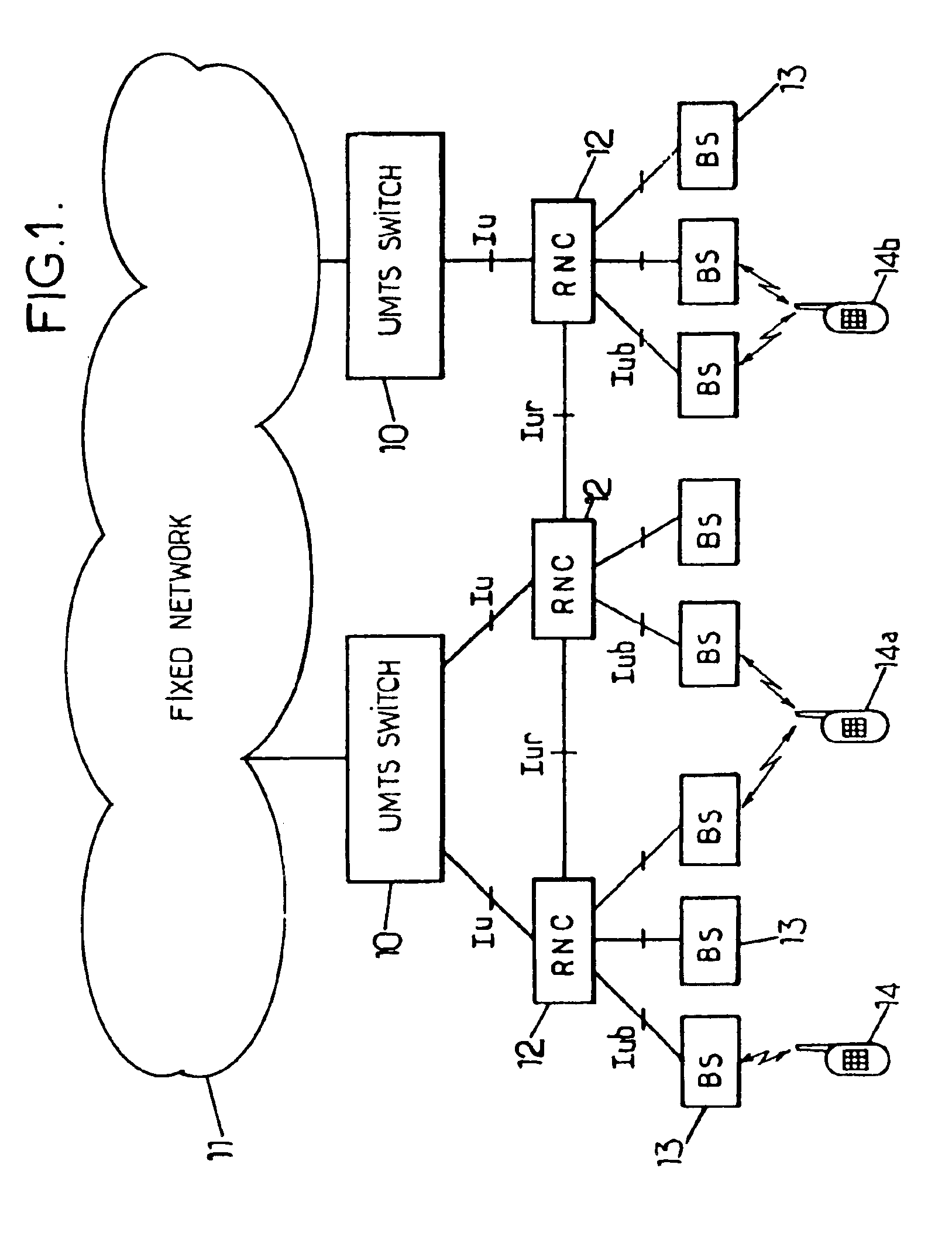
[0076]FIG. 4 shows a UMTS network infrastructure for supporting the mode of macrodiversity between several SRNSs. The infrastructure sketched has a deliberately simplified configuration to clarify the explanation of the invention. The core network comprises a mobile service switch (MSC, “Mobile service Switching Centre”) 30 for the circuit mode, linked by Iu interfaces to two radio network subsystems (SRNS) each having an RNC 40, 41. The two RNCs 40, 41 communicate with one another via an Iur interface and respectively monitor base stations 50, 51 (node B) through Iub interfaces.

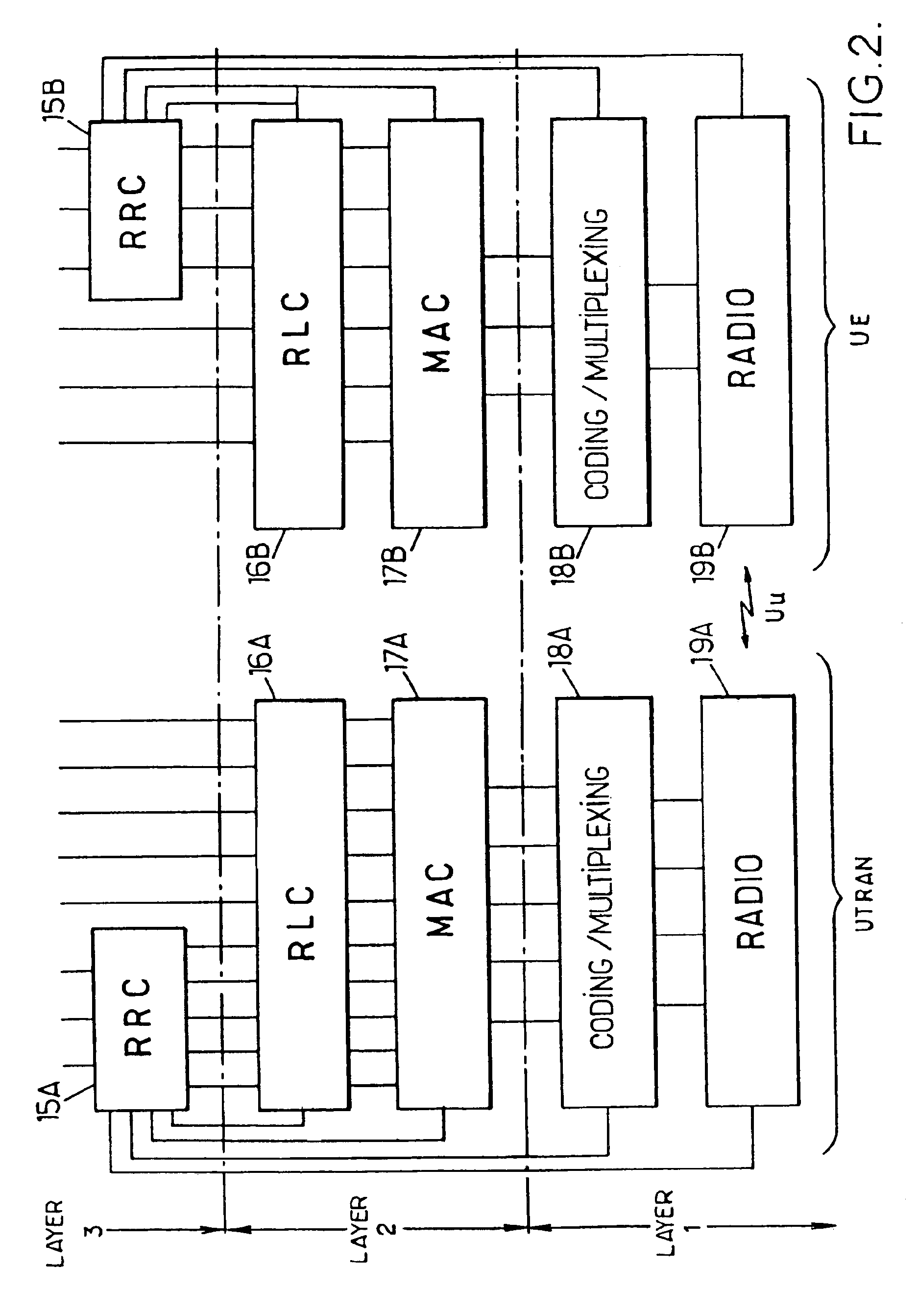
[0077]FIGS. 5 to 8 show active communication paths between the core network and UE 14 when the latter is moving. In the situation of FIG. 5, a first path has been established in a conventional manner between the MSC 30 and the UE 14 through the RNC 40 playing the role of SRNC and the base station 50. The SRNC 40 and the UE each have an MAC instance which, for each dedicated logical channel in circuit mode an...


PUM


Abstract

The infrastructure has a core network, radio network controllers linked to the core network and base stations provided with radio interfaces and each linked to one of the controllers. Ciphered information is transmitted over a first communication path in circuit mode between the core network and the terminal, passing through a first master controller, then over a second communication path in circuit mode between the core network and the terminal, passing through a second master controller. The second path is established in a transfer procedure comprising the transmission of adjustment data from the first to the second master controller and the suppression of the first path. These data are representative of a current value of a sequence number used to encipher the information and incremented at regular intervals, and of an offset between this sequence number and a time reference available to the second controller.

Description

BACKGROUND OF THE INVENTION[0001]The present invention relates to the field of radiocommunications, and in particular to the ciphering techniques used in cellular networks.[0002]The invention finds application in particular in third-generation cellular networks of the UMTS type (“Universal Mobile Telecommunication System”) using code division multiple access (CDMA) techniques.[0003]The invention is described hereinbelow in its application to a UMTS network, of which FIG. 1 shows the architecture.[0004]The switches of the mobile service 10, belonging to a core network (CN), are linked on the one hand to one or more fixed networks 11 and on the other hand, by means of a so-called Iu interface, to control equipment 12 or RNCs (“Radio Network Controllers”). Each RNC 12 is linked to one or more base stations 13 by means of a so-called Iub interface. The base stations 13, distributed over the territory covered by the network, are capable of communicating by radio with the mobile terminals...

Claims


Application Information

Patent Timeline
IPC IPC(8): H04Q7/38H04L9/08H04L9/16H04W12/00H04W36/12
CPCH04L63/0457H04W12/02H04W80/02H04W12/03
Inventor FAUCONNIER, DENISMOUSSET, CLAIRE
Owner ALCATEL LUCENT SAS
Why Eureka
Try Eureka