Waveform measuring instrument using equivalent time sampling

a waveform and measuring instrument technology, applied in instruments, noise figures or signal-to-noise ratio measurement, cathode-ray oscilloscopes, etc., can solve the problems of reducing the number of data item points that can be displayed on the waveform display screen, and the reproduction and display of the original waveform may be almost impossible, so as to achieve the effect of improving the reproducibility of the waveform

Inactive Publication Date: 2005-06-21
YOKOGAWA ELECTRIC CORP
View PDF8 Cites 15 Cited by
  • Summary
  • Abstract
  • Description
  • Claims
  • Application Information

AI Technical Summary

Benefits of technology

[0020]The present invention intends to solve these problems, with the objective of improving the reproducibility of waveforms in the waveform measuring instruments that use equivalent time sampling.
[0022]This enables each measured data item to be written in the acquisition memory without the later measured data being overwritten on the prior measured data, even if different voltage values are sampled in the same time slot, and thus the reproducibility of waveforms can be improved.

Problems solved by technology

However, in digital oscilloscopes having a conventional configuration as shown in FIG. 1, there is a problem that, if different voltage values are sampled for the same time slot, the prior measured data item is overwritten by the later measured data item and thus the prior measured data item is not recorded because only one data item can be recorded at an instant.
In addition, if zoomed waveforms of such signals are displayed, intervals between displayed data items are extended and thus the number of data item points that can be displayed on a waveform displaying screen decreases because of the limitation in resolution of the time interval measurement circuit, and this may possibly cause those waveforms not to be recognized as a time series continuous waveform group. FIG. 4 shows an example of such waveforms.
If such a situation occurs, reproduction and display of the original waveforms may be almost impossible.

Method used


Image

  • Waveform measuring instrument using equivalent time sampling
  • Waveform measuring instrument using equivalent time sampling
  • Waveform measuring instrument using equivalent time sampling

Examples


Embodiment Construction

[0030]An embodiment of the present invention will be described below with reference to the drawings.

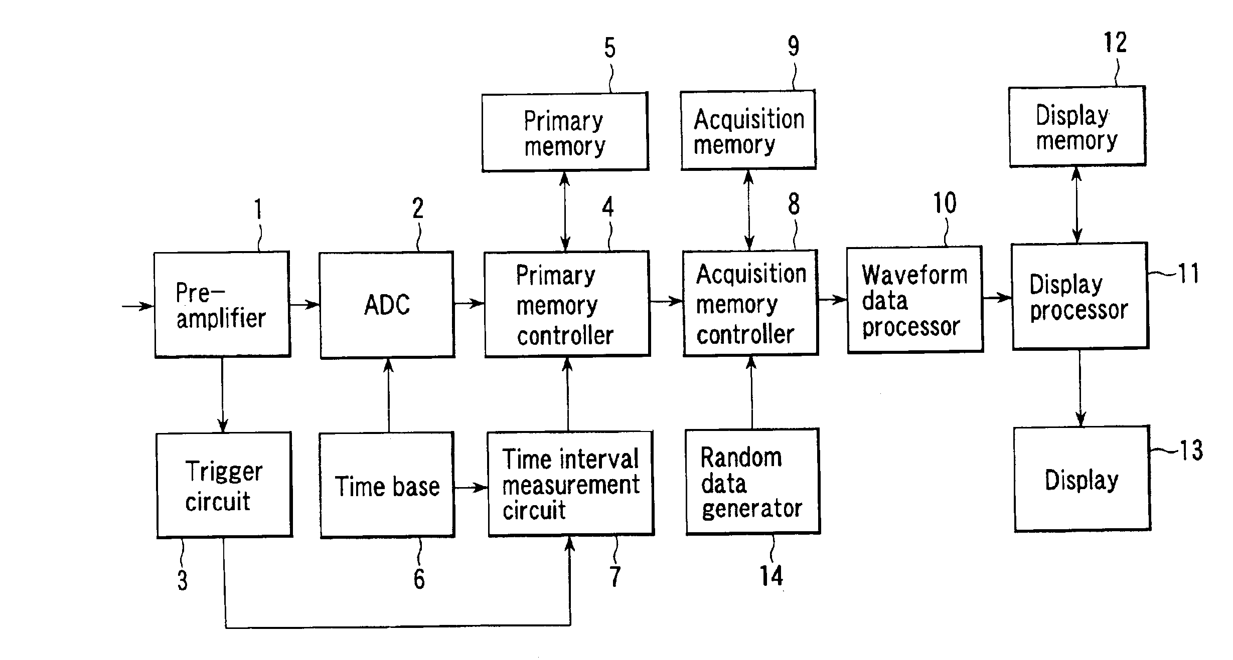
[0031]FIG. 5 is a block diagram of a waveform measuring instrument showing an embodiment of the present invention, and the parts common to those in FIG. 1 are given the same signs. In FIG. 5, random data generator 14 is connected to acquisition memory controller 8. This random data generator 14 controls in what order the data items are to be recorded in predetermined regions of acquisition memory 9.

[0032]Acquisition memory 9 used in the present invention is divided into a plurality of time slot regions corresponding to the interval of equivalent time sampling and a plurality of memory address groups is assigned to each time slot region.

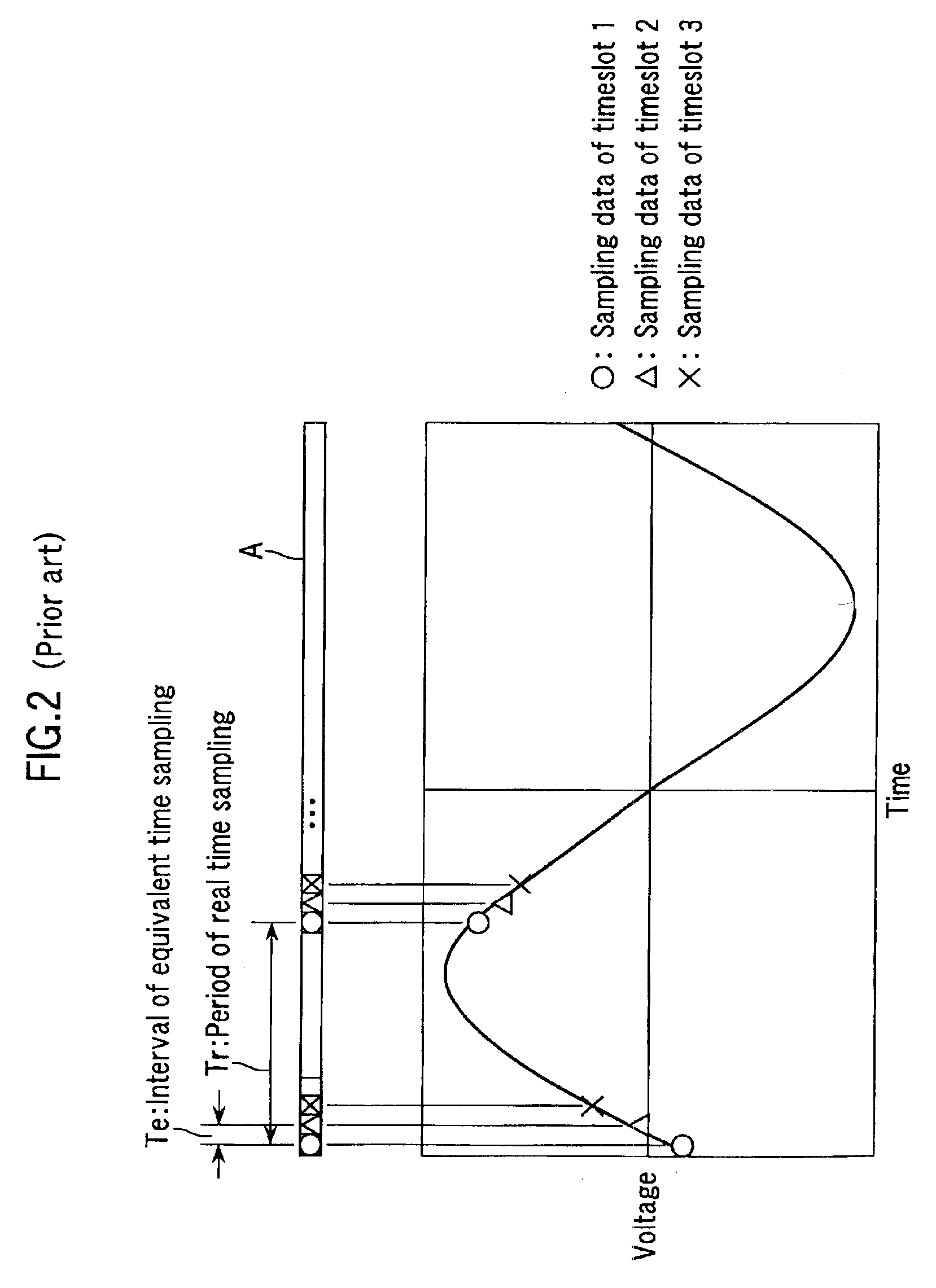
[0033]FIG. 6 is a drawing illustrating the relationship between the waveform data items and acquisition memory 9 in the present invention. In FIG. 6, symbol “◯” represents the sampling data items in time slot 1, symbol “Δ” represents the sampling data i...


PUM


Abstract

The present invention is intended to provide a waveform measuring instrument whose waveform reproducibility in the equivalent time sampling system is improved.The present invention is characterized by that, in a waveform measuring instrument configured so that the repeated waveform data items are acquired and sent to the acquisition memory by means of the equivalent time sampling, the above acquisition memory is divided into a plurality of time slot regions corresponding to the interval of equivalent time sampling and a plurality of memory address groups is assigned to each time slot region.

Description

BACKGROUND OF THE INVENTION[0001]1. Field of the Invention[0002]The present invention relates to the improvement of waveform measuring instruments using equivalent time sampling, such as digital oscilloscopes.[0003]2. Description of the Prior Art[0004]The digital oscilloscope which is a typical waveform measuring instrument converts a time-series continuous signal waveform into digital data with an A / D converter, records the data in a memory discretely, and displays the data recorded in the memory as waveforms.[0005]In such waveform measuring instruments, there is a repeated data acquiring mode (hereafter called “repeated mode”) using equivalent time sampling as one of the methods for recording signal waveforms on the memory.[0006]FIG. 1 is a block diagram showing a conventional embodiment in which the repeated mode function of the digital oscilloscope is considered.[0007]Pre-amplifier 1 comprises the attenuation circuit and the pre-amplifier and adjusts the amplitude of input signa...

Claims


Application Information

Patent Timeline
Patent Type & Authority Patents(United States)
IPC IPC(8): G01R13/20G06F19/00G01R13/02G01R13/34
CPCG01R13/345G01R13/02
Inventor SAITOU, TAKUYATAKEZAWA, SHIGERU
Owner YOKOGAWA ELECTRIC CORP
Why Eureka
Try Eureka