All-suspension bicycle frame with isolated drive gear

a drive gear and bicycle frame technology, applied in the direction of bicycles, unicycles, motorcycles, etc., can solve the problems of reducing suspension, affecting the stability of the bicycle frame, so as to reduce the displacement of the bicycle and reduce the suspension. , the effect of reducing friction, reducing vibration and reducing the movement of the bicycl

Inactive Publication Date: 2005-06-28
HALS CATO
View PDF17 Cites 60 Cited by
  • Summary
  • Abstract
  • Description
  • Claims
  • Application Information

AI Technical Summary

Benefits of technology

[0030]It is often attempted to dampen undesirable rocking movements by supplying the movable parts with friction against each other somewhere and to a controllable degree. The submitted invention has solved this by utilizing the possibility for precise adjustment of the suspension mechanism in such a way that the counterforces in the spring do not surpass the counterforces represented by the bicyclist and the bicycle, while simultaneously minimizing friction and providing a favourable direction of the wheel at the initiation of each movement. Together, these characteristics ensure that virtually no movement is transplanted to the handlebars, which provides the bicyclist with an upwards thrust. Accordingly, there will be no mass in need of suspension. This applies to most situations at most speeds. In certain occasions, where bumps and velocity demand a stronger spring for shock absorption, a supplementary suspension medium has been included in addition to the main medium. At low speeds, low weight, and simple manuvering, no additional friction to the suspension system is required. Quite the contrary, as long as the spring is soft enough and the speed and weight are low enough, no movement will propagate through the handlebars. Should this occur, no suspension is needed anyway, as there is no mass in movement. For this reason, no dampening mechanism is included in the present embodiment.

Problems solved by technology

The disadvantage of this type of construction is a considerable shaking of the bicyclist's feet and legs at high speeds.
Another disadvantage is the generally upwards movement of the rear wheel and chainstays upon hitting a bump in the road.
For all practical purposes, this results in a compromise between displacement of the bicyclist and reduced suspension.
This, however, involves a significant amount of energy, and the system as a whole is forced to compromise (provided this accelerations' increased demand for friction against the surface does not cause the rear wheel to lose its grip), by partly providing suspension, and partly lifting the bicyclist up.
The drawback of this construction is the resulting variable distance between the topmost part of one of the (most commonly) three cogwheels of the crank set, and the upper quadrant of the corresponding cogwheel on the freewheel.
This leads to a stretching of the chain, exerting power which in its turn saps the energy the bicyclist is utilizing to propel the vehicle forwards.
This is the problem which bicycles with isolated power transmission try to eliminate.
Furthermore, the wheel's direction immediately after impact with a bump on the surface remains unfavorable.
A general drawback and limitation that all full-suspension solutions presently suffer is a comparatively large amount of weight which remains unsuspended.
An ideal function such as bicycling over medium-sized bumps at high speed is not possible with this type of construction, for two reasons.
Firstly, the chain and rear changer are forced to move with the wheel, making the chain rattle to and fro and provoke unexpected changes of gear.
Rather, the bicyclist again is forced to absorb the shock through the saddle, as excessive friction in the system prevents the spring in the springing mechanism from compressing, which is caused by the speed with which, for example, oil is pressed through a valve too high for the reciprocal power to provide sufficient suspension for the bicyclist.
The disadvantage of this, and related solutions, is the reduction of the number of gears by 66%.
However, this much friction or suppression prevents the rear wheel from returning to its intended position in time to absorb the shock from the next bump in the road (unless this is situated several meters away).
Such a design will not provide any “anti-dive” feature.
This is not desirable.
A problem all these fork constructions have in common, is that it is imperative to take them apart, replace the springing medium with another one, such as a stiffer spring, to attain a satisfactory result based on the individual bicyclists weight and preferred cycling style.
These solutions will normally be poorly suited to bicycles.
However, this mechanism, which is not very clearly described in the document, either provides too small a range of fork travel, or is structurally weak regarding torsional forces.
In addition, it is unclear how the suspension means can work as intended.
This solution requires a considerable amount of space under the fork crown in order to accommodate the middle central bar, as well as ample dimensions and weight for parts which are to absorb shock.

Method used


Image

  • All-suspension bicycle frame with isolated drive gear
  • All-suspension bicycle frame with isolated drive gear
  • All-suspension bicycle frame with isolated drive gear

Examples


Embodiment Construction

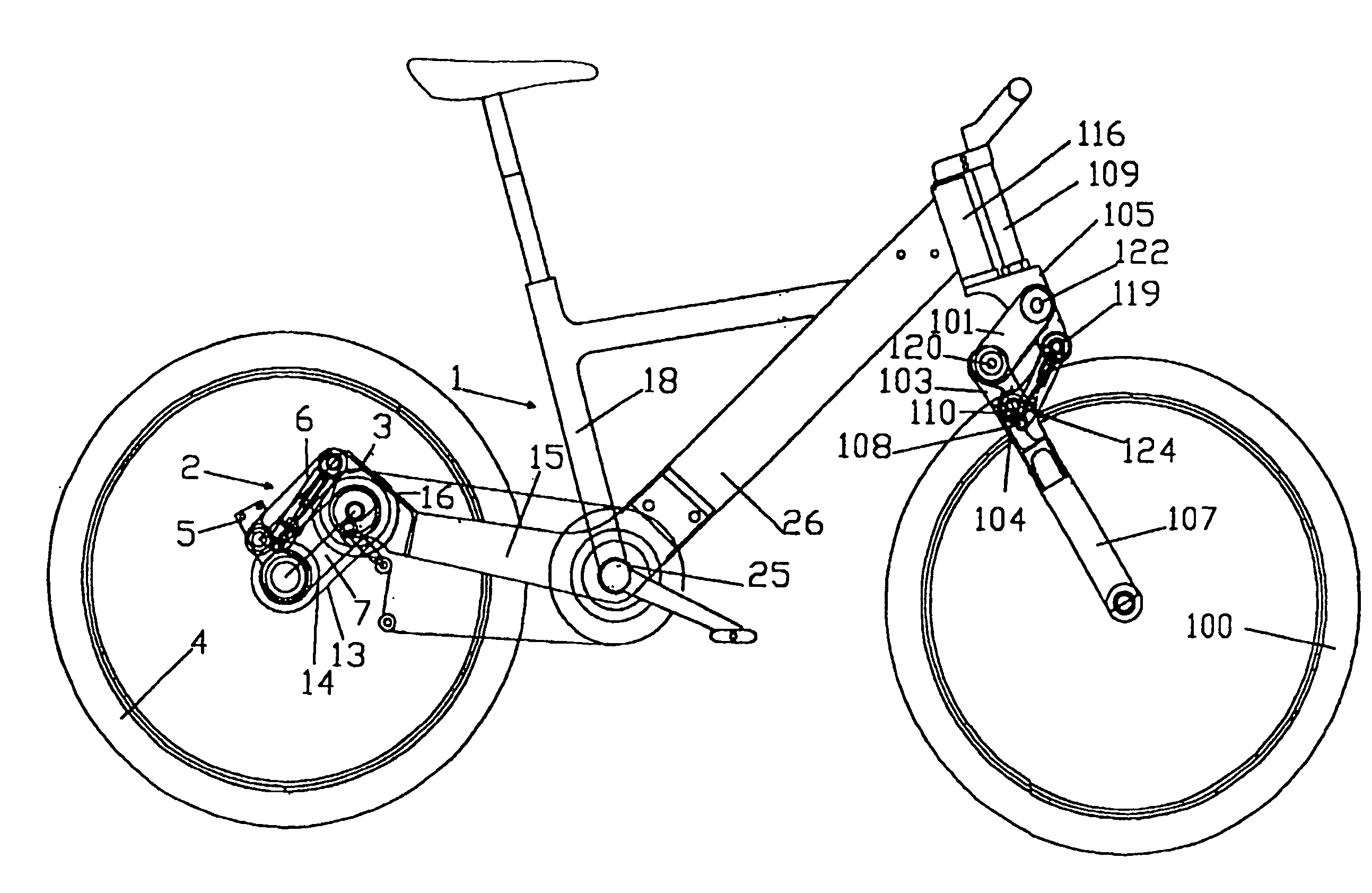
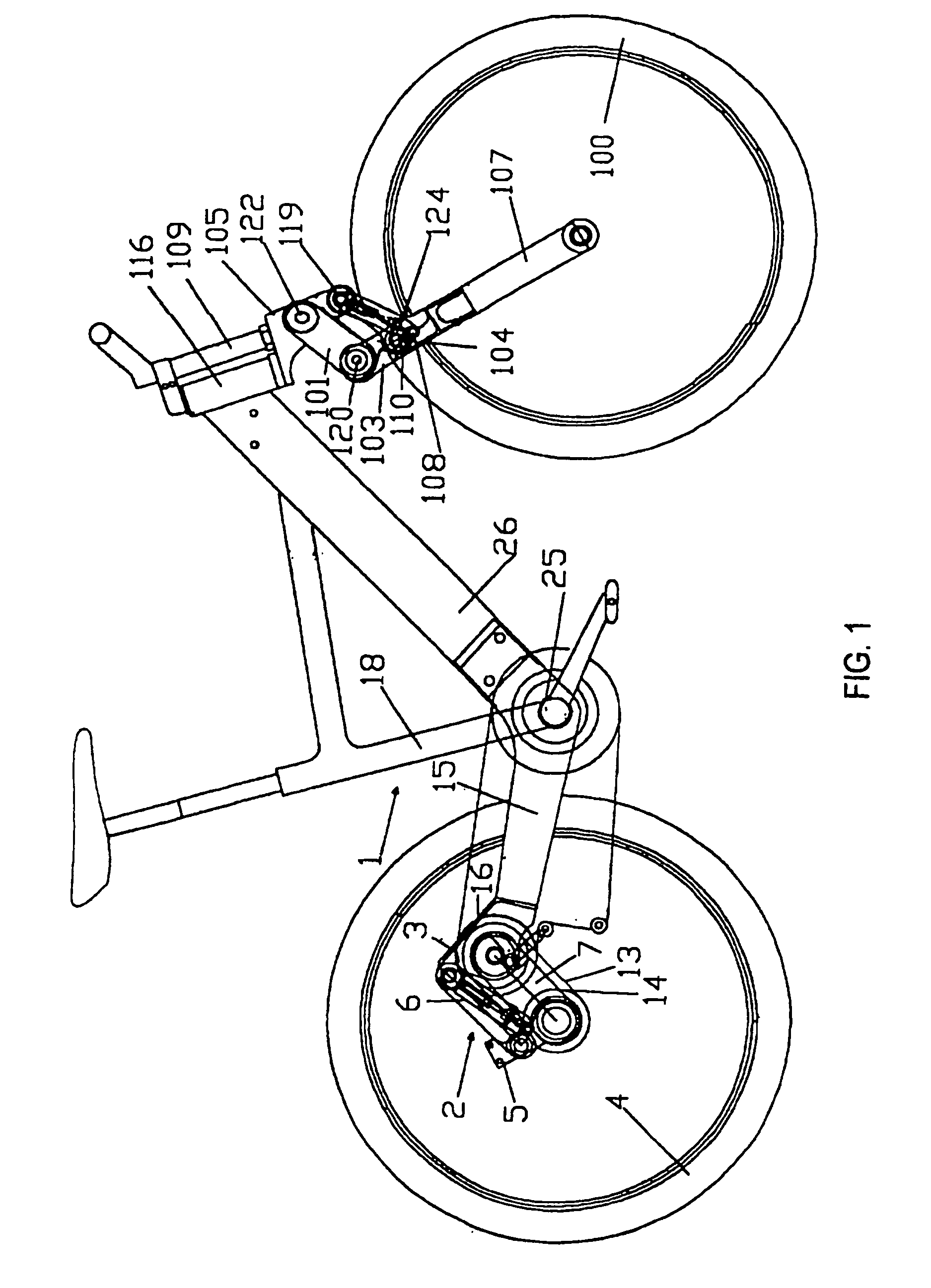
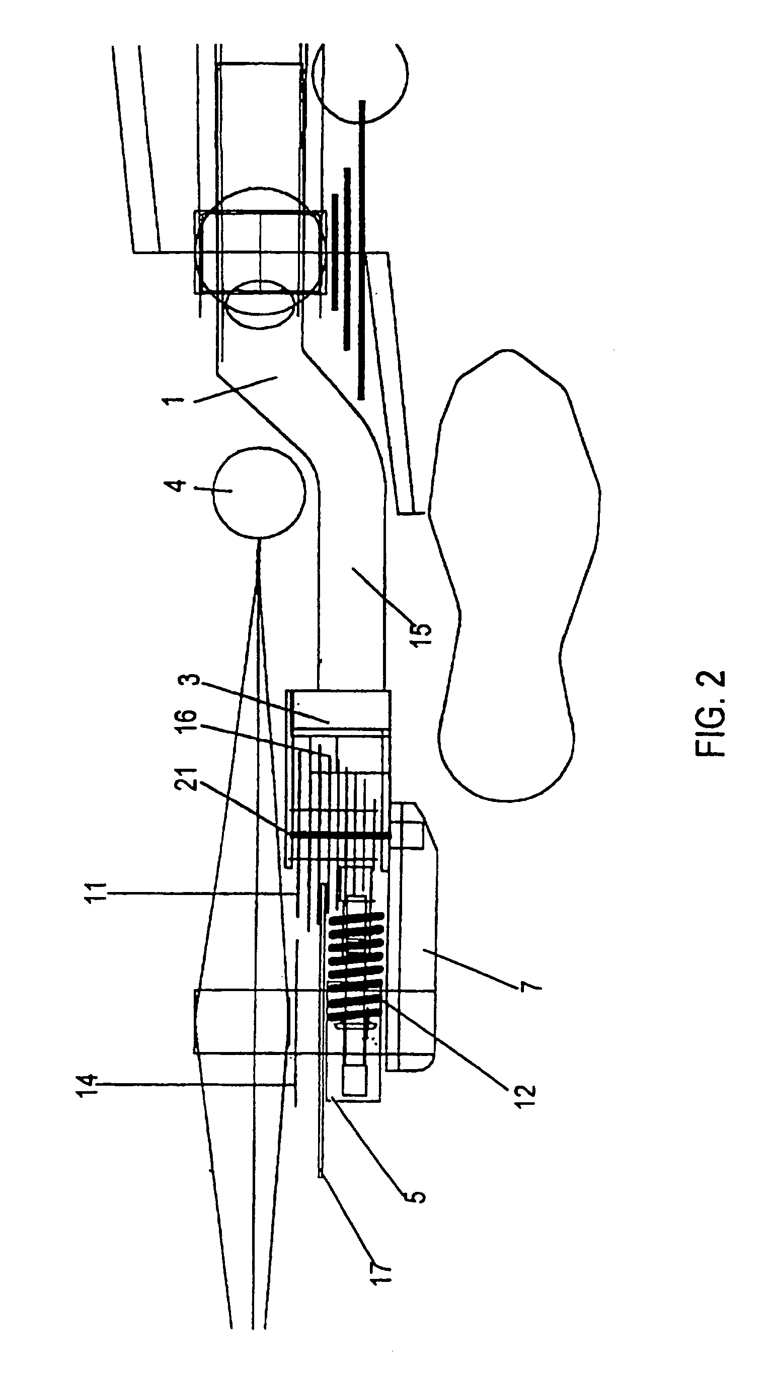
[0040]FIGS. 1–3 show a preferred embodiment of one aspect of the invention. A rear frame construction 2 includes a lower wheelholder 5 for rear wheel 4, rear fastening part 3 attached to a main frame 1, one movable midsection formed of bars 6, 7, between wheel holder 5 and fastening part 3, and the frame itself 1 for supporting the remaining parts which together comprise a bicycle (i.e., a two-wheeled vehicle). As shown in FIG. 1, the main frame 1 includes chainstays 15, saddle tube 18, crank housing 25, and a lower tube 26 connecting the crank housing 25 to steering tube 116.

[0041]Rear fastening part 3 should be mounted on the chainstays (chain fork) 15 of the main frame 1, and they strengthen the chainstays 15 with mounting details because the rear fastening part 3 has holes for threaded inserts for the fastening of bearing bolts 21, 22 as well as threaded parts for mounting of gears. Fastening part 3 forms a rigid extension of chainstays 15.

[0042]The bicycle's rear wheel 4 is mou...


PUM


Abstract

A frame assembly for a two-wheel vehicle includes a front wheel fork and chainstays. Between the front wheel fork and the chainstays, the frame assembly further includes a saddle tube, a crank housing, and a lower tube connecting the crank housing to a steering tube. A parallelogram-shaped suspension assembly is attached to a rear end of the chainstays.

Description

THE INVENTION[0001]This invention pertains to a suspension system and power transmission on a two-wheeled vehicle, predominantly a bicycle or motorcycle. More precisely put, the invention pertains to a suspension system for the rear wheel and the power transmission, as well as a suspension fork assembly.A DESCRIPTION OF RELATED TECHNOLOGY[0002]There are a number of existing prior art suspension designs for bicycle wheels. Recent variations include one in which the entire power transmission is mounted in the bicycle's rear frame triangle, also called chainstays, which in turn are mounted to the main frame with a joint. The suspension allows the chainstays to move relative to the main frame, provided the chainstays have been joined at an appropriate point to the main frame. It follows that as the rearwheel hits a bump, the entire rear triangle of the bicycle will change its position relative to the main frame, thus isolating the main frame from the impact. The impact, in other words, ...

Claims


Application Information

Patent Timeline
Patent Type & Authority Patents(United States)
IPC IPC(8): B62K25/20B62K21/20B62K25/24B62K21/00B62K25/04
CPCB62K21/20B62K25/24B62K25/20
Inventor HALS, CATO
Owner HALS CATO
Why Eureka
Try Eureka