Headlight

a headlight and headlamp technology, applied in the field of lamps, can solve the problems of poor design, poor visibility from oncoming vehicles, and lowering the utilization factor of beams with respect to light sources, and achieve the effects of improving visibility, improving performance, and excellent

Inactive Publication Date: 2005-06-28
STANLEY ELECTRIC CO LTD
View PDF11 Cites 20 Cited by
  • Summary
  • Abstract
  • Description
  • Claims
  • Application Information

AI Technical Summary

Benefits of technology

[0028]According to the present invention as above, the direct light from the light source, which has been useless in the prior art, is corrected using the second reflecting surface and the third reflecting surface and is then directed in the illumination direction in a state where the shape or the like of light is controlled so as to be utilized in the formation of light distribution characteristics. Therefore, the brightness of such a kind of the headlight can be increased, so that the present invention exerts an extremely superior effect on the improvement of performance such as the improvement of visibility.
[0029]Furthermore, the recovery of direct light has an excellent effect on the decrease in harmful light to be irradiated to the outside or effect on preventing the generation of dazzling. In addition, the emitting area of the headlight may also be increased by the second and third reflecting surfaces, so that the visibility from the oncoming vehicle, pedestrian, or the

Problems solved by technology

Therefore, there is a problem of poor visibility from an oncoming vehicle, a pedestrian, or the like.
As a result, there is another problem of lowering the

Method used


Image

  • Headlight
  • Headlight
  • Headlight

Examples


first embodiment

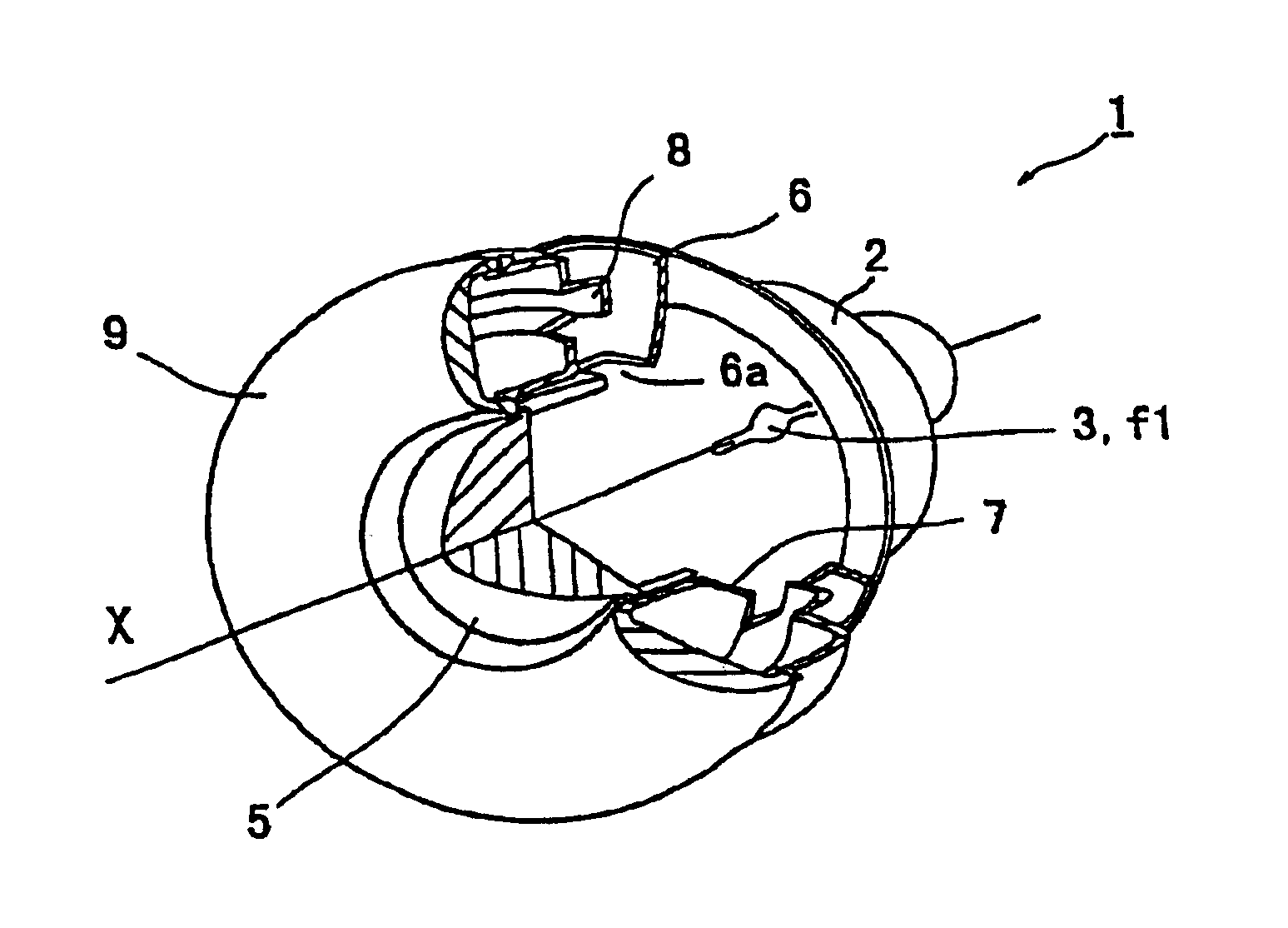
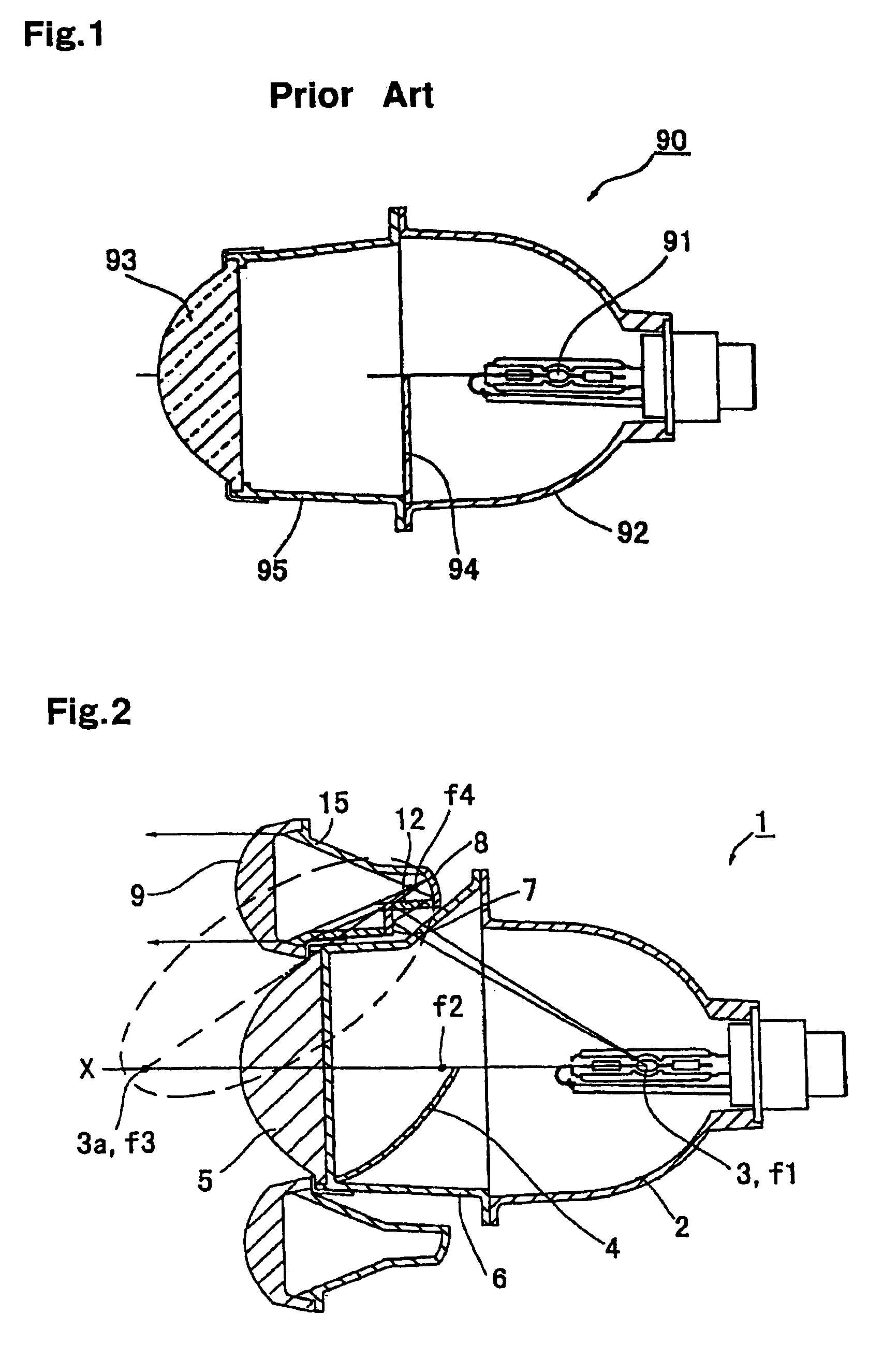
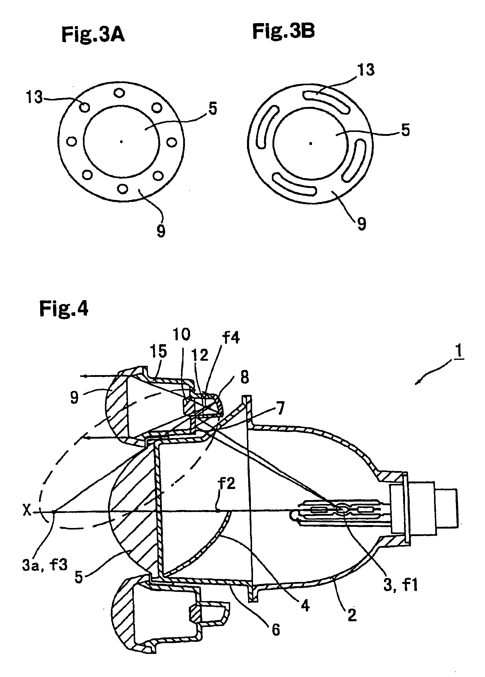
[0045]Referring now to FIG. 2, there is shown a headlight denoted by the reference numeral 1 as the present invention. The headlight 1 includes an ellipse group reflecting surface 2, a light source 3, a shielding plate 4, a projection lens 5, and a lens holder 6. The ellipse group reflecting surface 2 has a major axis provided as a rotational axis which coincides with the axis X of the headlight 1 (axis passing through the center of the headlight 1). That is, such a surface 2 is obtained by rotating an ellipse around the rotational axis, so that the surface 2 can be used as a main reflecting surface. The light source 3 is located at a position substantially corresponding to a first focus f1 of the ellipse group reflecting surface 2. The shielding plate 4 is positioned in the vicinity of a second focus f2 of the ellipse group reflecting surface 2. The projection lens 5 is arranged coaxially on the axis X. In addition, the projection lens 5 is attached on the ellipse group reflecting ...

sixth embodiment

[0080]Referring now to FIG. 10, there is shown the present invention. In this embodiment, the configuration of a headlight which employs a projection system is the same as that of each of the embodiments described above, except that a fourth reflecting surface 19 is formed in this embodiment instead of the second and third reflecting surfaces 7 and 8 in the other embodiments described above.

[0081]The fourth reflecting surface 19 is provided for capturing direct light from a light source 3 to a lens holder 6 that connects an ellipse group reflecting surface 2 with a projection lens 5 in the headlight which employs the projection system. For instance, the fourth reflecting surface 19 is seamlessly connected with the ellipse group reflecting surface 2. At this time, an opening may be formed in the optical path extending from the light source 3 to the fourth reflecting surface 19 just as in the case with the first embodiment, or the lens holder 6 may be made of a transparent material. F...


PUM


Abstract

A headlight having an ellipse group reflecting surface as a main reflecting surface and a projection lens further includes a second reflecting surface, a third reflecting surface, and a ring-shaped lens. Direct light from a light source reaching to a space between the main reflecting surface and the projection lens is reflected by the second reflecting surface backward. The reflected light from the second reflecting surface is further reflected by the third reflecting surface, and then is adjusted with the ring-shaped lens. Light directly emitted from the light source and being ineffective in the conventional headlight can be collected using the second and third reflecting surfaces, and forwarded in an illumination direction by passing through the ring-shape lens such that the shape of the light is controlled to provide an appropriate shape, thereby contributing to the formation of light distribution characteristics and increase in the light intensity.

Description

[0001]This invention claims priority benefit to Japanese Patent Applications No. 2002-250351, filed on Aug. 29, 2002, and Japanese Patent Applications No. 2002-72095, filed on Mar. 15, 2002, the disclosures of which are hereby incorporated by reference.BACKGROUND OF THE INVENTION[0002]1. Field of the Invention[0003]The present invention relates to a lamp such as a headlight or a fog lamp mainly used for a lighting equipment of a vehicle. More specifically, the present invention relates to a lamp referred to as a projection lamp which adopts a reflecting mirror based on a curve of an ellipse having two focuses, a first focus and a second focus, where a cross sectional shape of light that converges to the second focus is projected in the illumination direction using a projection lens to obtain predetermined light-distribution characteristics of the lamp.[0004]2. Description of the Related Art[0005]FIG. 1 is a diagram that illustrates an exemplified configuration of a conventional lamp...

Claims


Application Information

Patent Timeline
IPC IPC(8): B60Q1/00B60Q1/04F21V5/00F21V7/00F21S8/10F21S8/12F21V11/16F21V11/00
CPCB60Q1/0052F21S48/1258F21S48/1275F21S48/1388F21S48/1283F21S48/145F21S48/1382F21S41/17F21S41/24F21S41/255F21S41/275F21S41/321F21S41/43F21S41/365F21S41/338F21S41/265
Inventor FUTAMI, TAKASHI
Owner STANLEY ELECTRIC CO LTD
Why Eureka
Try Eureka