Honey bee monitoring system for monitoring bee colonies in a hive

a honey bee and monitoring system technology, applied in the field of honey bee monitoring system for monitoring bee colonies in hives, can solve the problems of increasing the cost of maintenance, and increasing the difficulty of monitoring bee colonies, so as to improve the resolution, improve the resolution, and improve the degree of bee separation resolution

Inactive Publication Date: 2005-06-28
UNIVERSITY OF MONTANA
View PDF8 Cites 25 Cited by
  • Summary
  • Abstract
  • Description
  • Claims
  • Application Information

AI Technical Summary

Benefits of technology

[0009]The bee monitoring system of the subject invention can comprise a bee counter. A preferred embodiment of a bee counter is described which uses infra-red detectors and emitters mounted in ingress / egress passageways. Low cost, off-the-shelf emitters and detectors are combined with a microproccessor to separate and compute sequential signals to improve resolution. The subject counter uses an amplifier that conditions and eliminates false signals, a multiplexer and sampler with the capability of looking at only one passageway at a time, a hysteresis circuit, and de-bounce circuitry to remove bounce in the switching system. The entire system enables rapid and accurate polling of the detectors, achieving a high degree of bee separation resolution via the fast timing of the counting cycles.

Problems solved by technology

Honey bee colonies are susceptible to poisoning from pesticides and pollutants and thus the hives must be monitored daily.
Using current technologies, routine management of bee colonies requires time consuming on-site visual inspection of each hive.
Although this may not be a problem for a beekeeper with a few hives, it becomes a major cost factor to a beekeeper who makes most or all of his or her living by managing hundreds to tens of thousands of hives.
Virtually all of these devices are highly imprecise and require constant maintenance.
Programming the microprocessor is laborious and the unit is costly.
Although the BeeScan units are reliable, data from the counters can not be downloaded in continuous mode or ported to a communications network.
In addition, the counter pools all data from all of the 32 ingress / egress passageways, making it impossible to separate and compare sequential signals from each passageway.
No such system currently exists.

Method used


Image

  • Honey bee monitoring system for monitoring bee colonies in a hive
  • Honey bee monitoring system for monitoring bee colonies in a hive
  • Honey bee monitoring system for monitoring bee colonies in a hive

Examples


Embodiment Construction

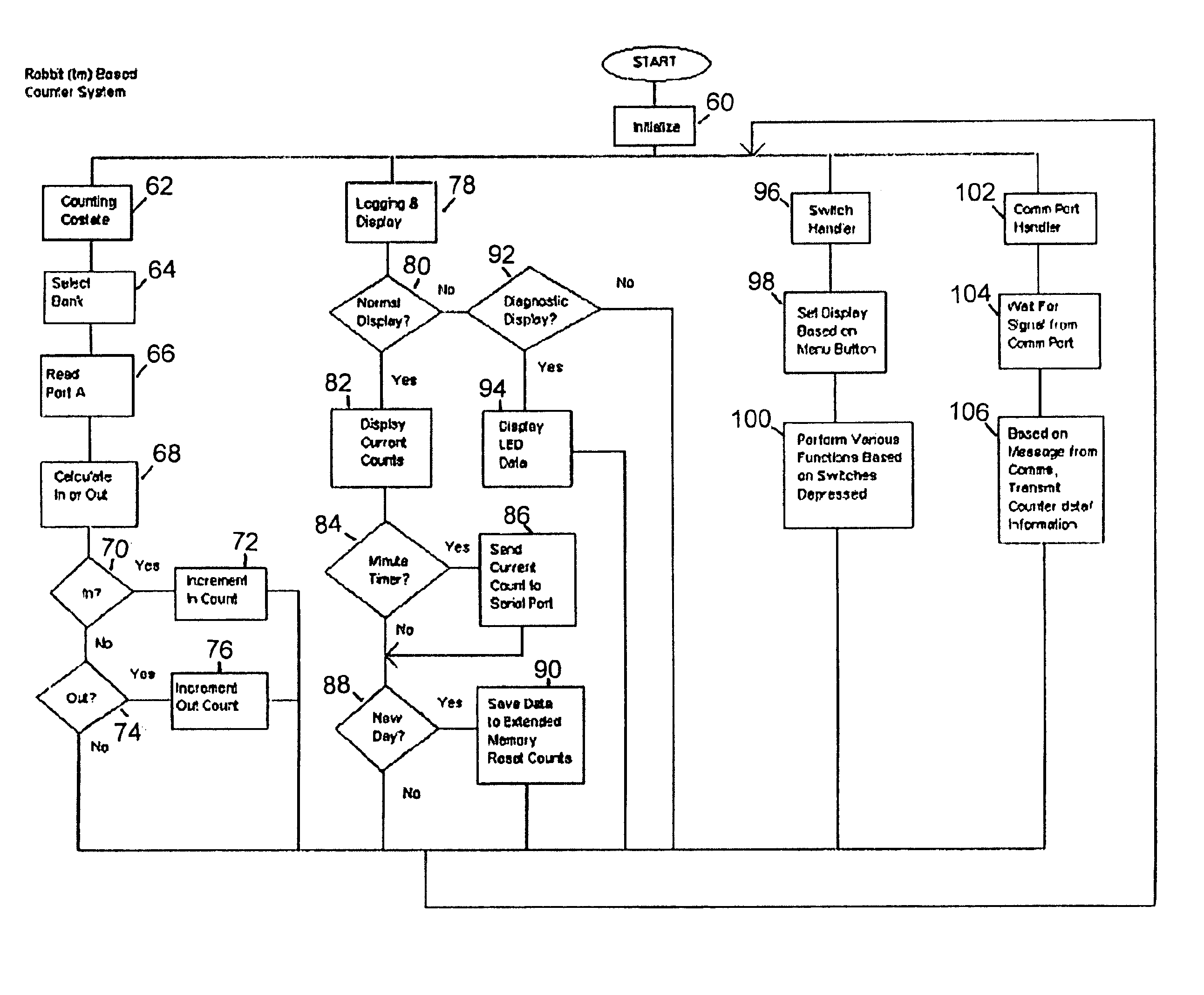
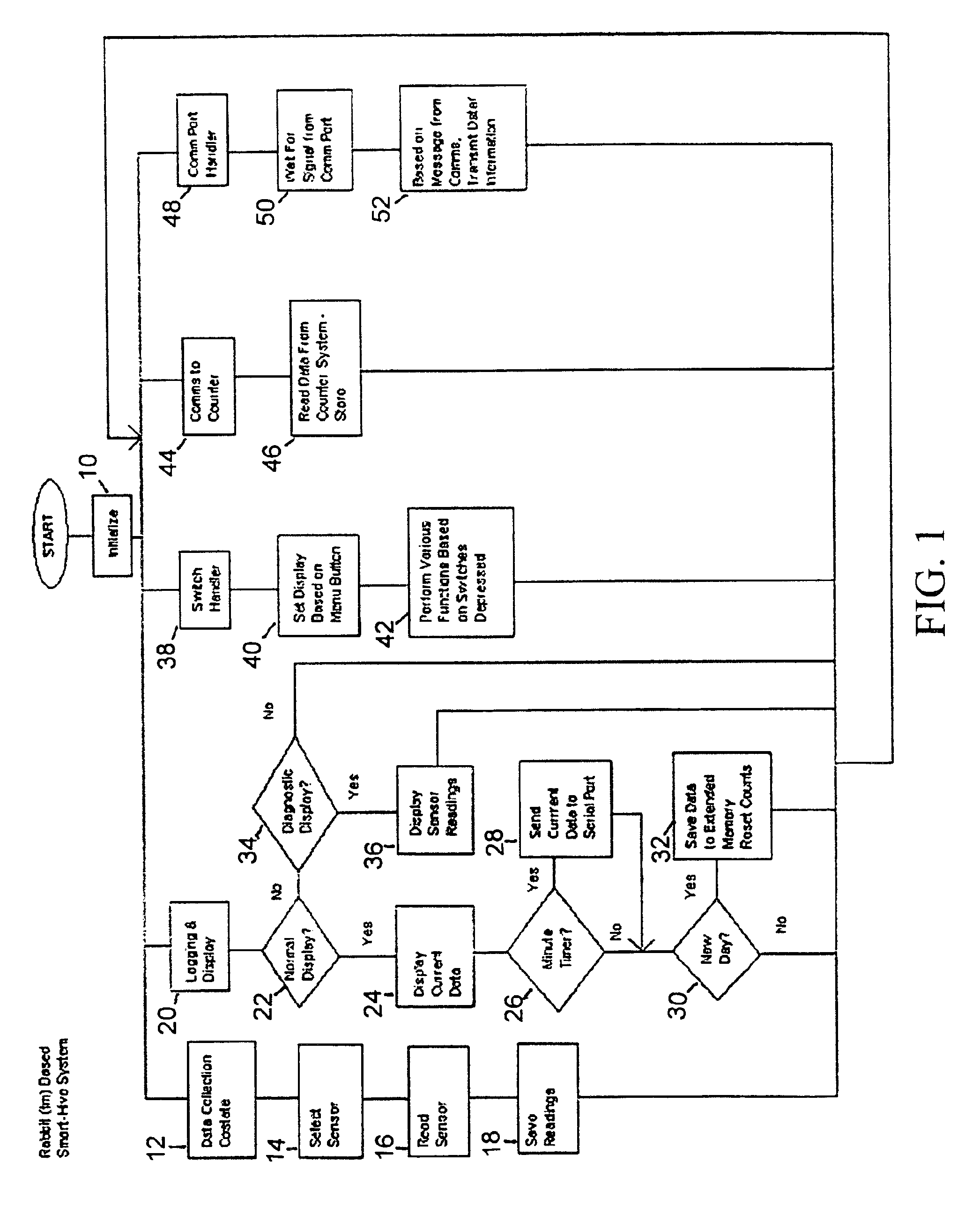
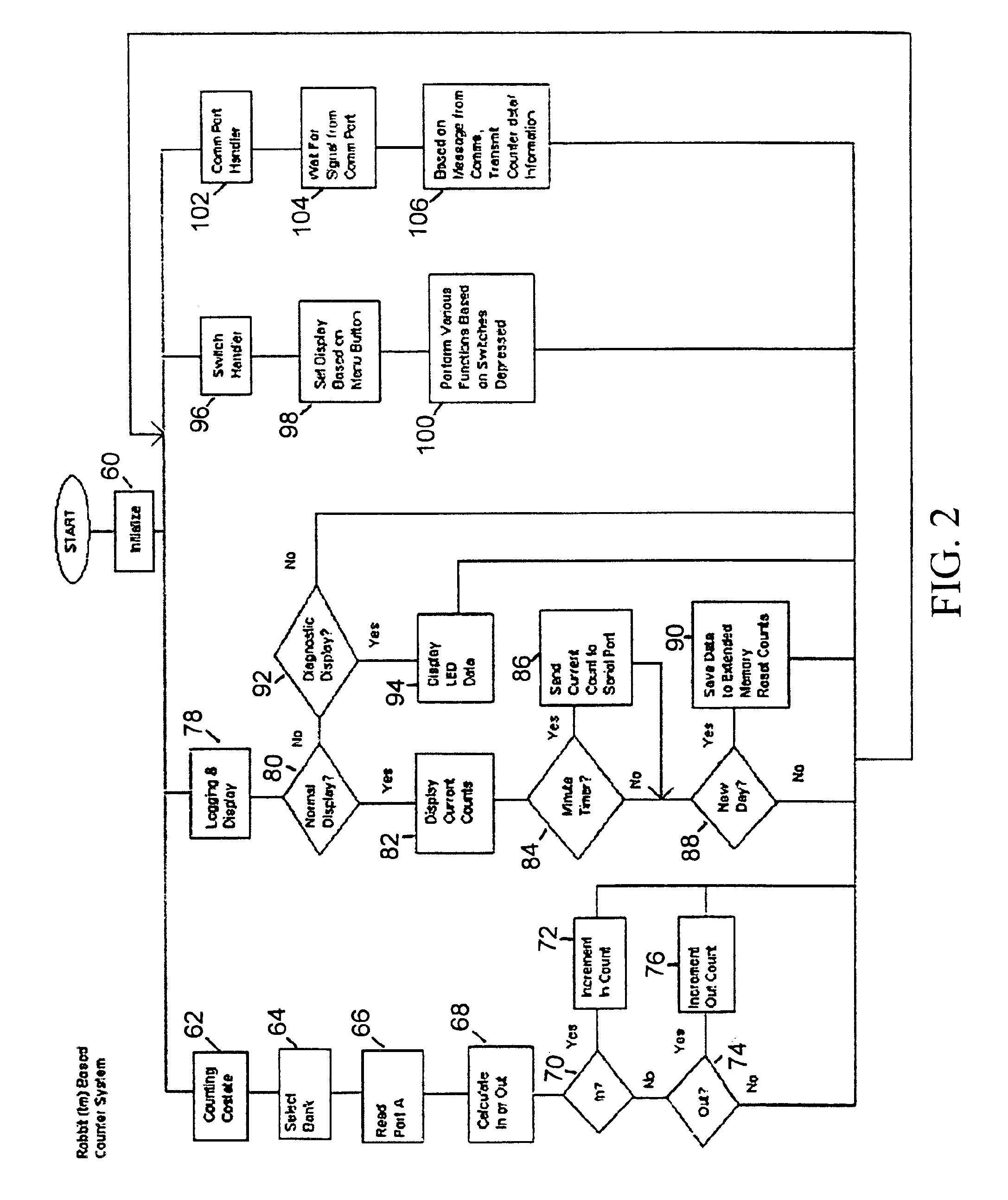
[0013]The bee monitoring system of the subject invention is an integrated system which collects data from multiple sensors and devices (probes, counter), combines and processes that data at the hive, controls external devices such as sampling pumps and analytical instruments, and communicates the results via a variety of means, including real-time or near real-time delivery via the internet.

[0014]The bee monitoring system of the subject invention has an associated microprocessor and LCD display. In addition, the data acquisition and controller system interfaces with multiple sensors to control or switch on and off sampling and communications systems. In total, this resulted in a rugged, versatile, and flexible system for monitoring a diverse and numerous array of sensors (temperature, load cell, relative humidity, bee counter, and other sensors as appropriate) and for controlling other devices, including sophisticated chemical and biological sampling and / or analysis instrumentation....


PUM


Abstract

An integrated bee monitoring system for monitoring bee colonies in a hive has a central microprocessor, at least two input transducers and at least two output signals. Input transducers include sensors which report the status of the colonies including colony weight, temperature, and relative humidity. A bee counter can also be included in the system to indicate colony activity. A bee counter is disclosed which uses an amplifying, multiplexer hysteresis and debounce circuitry to enable rapid and accurate polling of a single passageway. Information collected can be retrieved by read-out or liquid crystal display. Alternatively, information ca be retrieved by telephone line or wireless communications. The bee monitoring system also can remotely control peripheral devices such as feeders or chemical samplers.

Description

CROSS-REFERENCE TO RELATED APPLICATIONS[0001]This application claims the benefits of U.S. Provisional Patent Application Nos. 60 / 399,616, filed Jul. 30, 2002 and 60 / 400,034, filed Jul. 30, 2002. The disclosures of each of these applications are hereby incorporated by reference in their entirety, including all figures, tables and drawings.[0002]The subject invention was made with government support under a research project supported by the Defense Advanced Research Projects Agency (DARPA), Grant No. N66001-98-8630, Amendment #P0005 and the Space and Naval System Center. The government has certain rights in this invention.BACKGROUND OF THE INVENTION[0003]There are approximately 2.5 million honey bee colonies in the United States. These colonies increase crop yields by an estimated $12-14 billion. Honey bee colonies are susceptible to poisoning from pesticides and pollutants and thus the hives must be monitored daily. Further, pollination efficiency can be assessed and regulated by mon...

Claims


Application Information

Patent Timeline
Patent Type & Authority Patents(United States)
IPC IPC(8): A01K47/00A01K47/06A01K55/00A01K15/02A01K53/00A01K67/033
CPCA01K15/02A01K47/00A01K47/06F41H11/132A01K55/00A01K67/033A01K53/00
Inventor BROMENSHENK, JERRYSECCOMB, ROBERT A.RICE, STEVEN D.ETTER, ROBERT T.
Owner UNIVERSITY OF MONTANA
Why Eureka
Try Eureka