
Wavefront coding zoom lens imaging systems

a zoom lens and imaging system technology, applied in the field ofwavefront coding zoom lens imaging systems, can solve the problems of difficult to accommodate aberration in a zoom lens with few lenses, and achieve the effects of reducing the cost of the zoom lens imaging system, high quality, and fast zoom lens imaging

Inactive Publication Date: 2005-06-28
COLORADO UNIV OF RGT
View PDF105 Cites 105 Cited by
  • Summary
  • Abstract
  • Description
  • Claims
  • Application Information

AI Technical Summary

Benefits of technology

[0007]One feature herein is to provide a fast zoom lens imaging system with a reduced number of lens elements that provides high quality images over a large field of view, and at different zoom positions. Such a system enables simple and inexpensive fast wide-angle zoom lens with as few as two plastic elements. The cost of the zoom lens imaging system is directly reduced by minimizing the number of elements in the system and / or indirectly by reducing fabrication and assembly tolerances required to produce the system.

Problems solved by technology

In the prior art, such aberrations are not easily accommodated in a zoom lens with few lenses because of the large number of aberrations to be controlled and because of the changing parameters in the zoom imaging system.

Method used


Image

  • Wavefront coding zoom lens imaging systems
  • Wavefront coding zoom lens imaging systems
  • Wavefront coding zoom lens imaging systems

Examples


Embodiment Construction

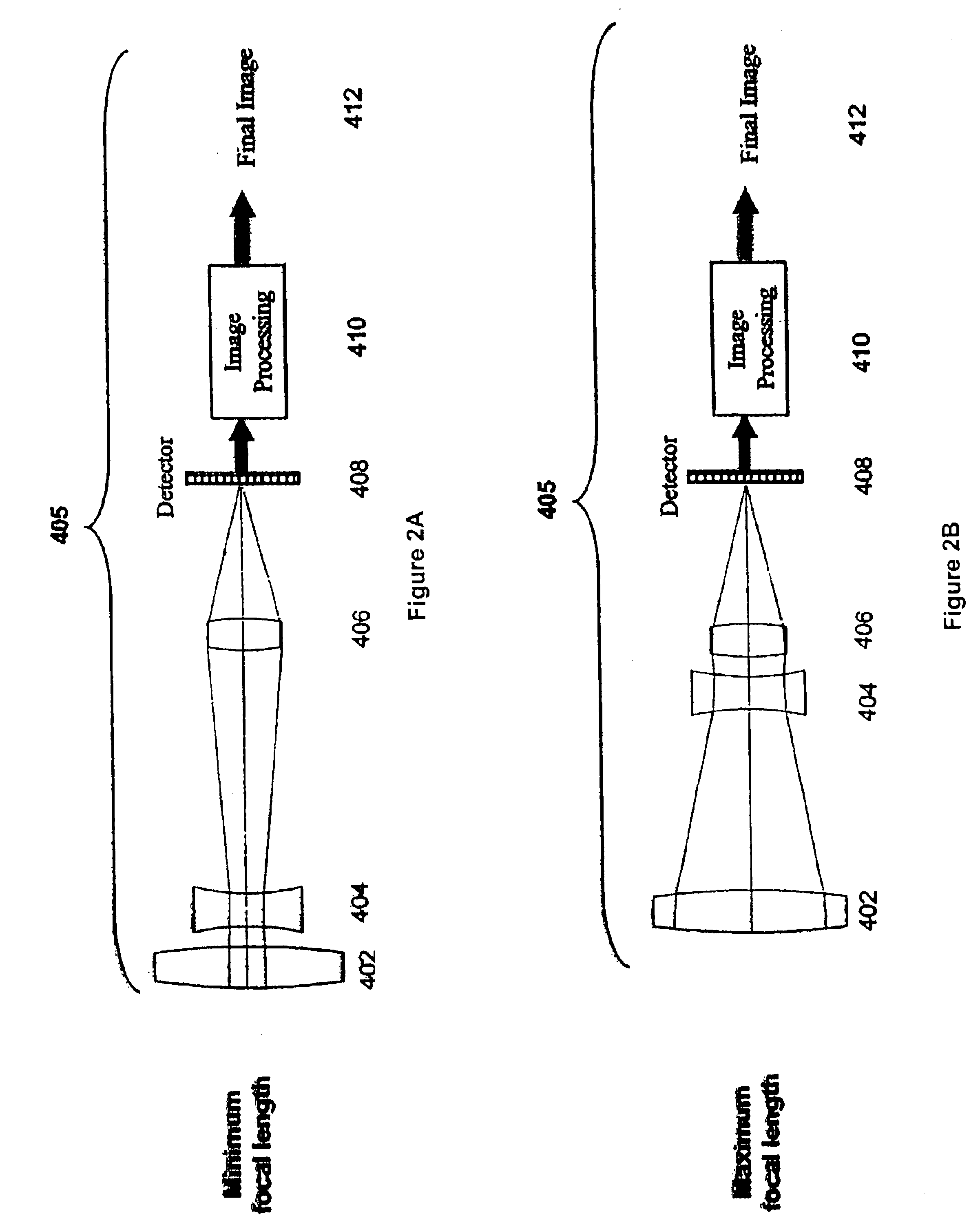
[0025]By coding the image forming wavefront and performing image processing on the resulting images zoom lenses can be designed that are very fast (small F / #) with a reduced number of optical elements. These zoom lenses can also have a very wide field of view and the equivalent of a flat image plane. By coding the wavefront and using image processing the zoom system can have an increased the depth of field and depth of focus well as reduced system sensitivity to misfocus aberrations. The extension of the depth of focus also means that the zoom lens can be made insensitive to temperature changes. In a similar fashion, manufacturing and assembly tolerances can be relaxed so that the accuracy with which the optics and detector array must be placed is reduced.

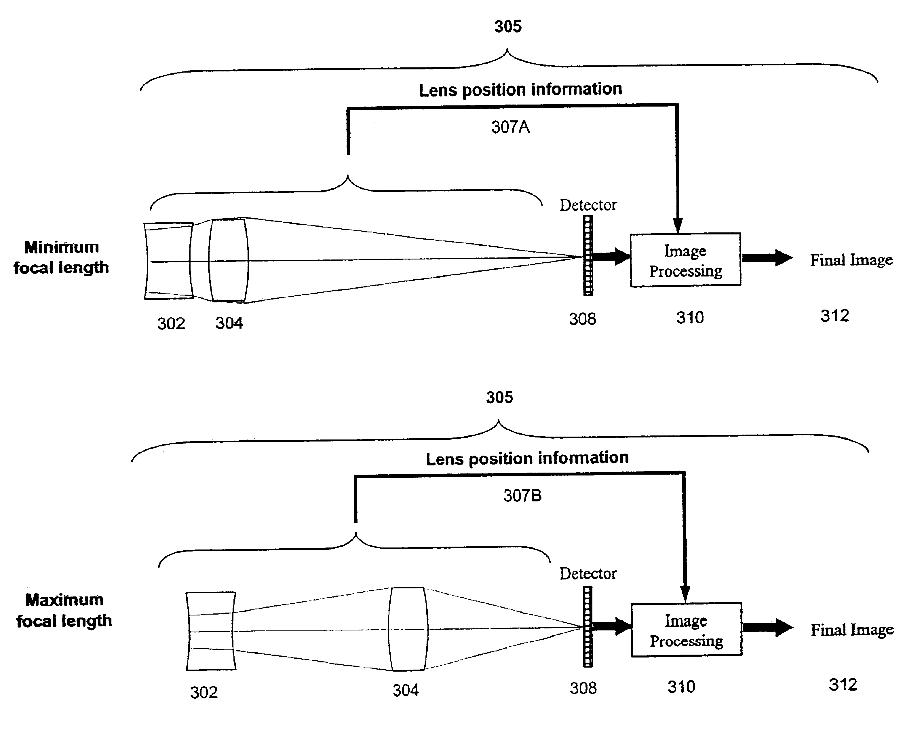
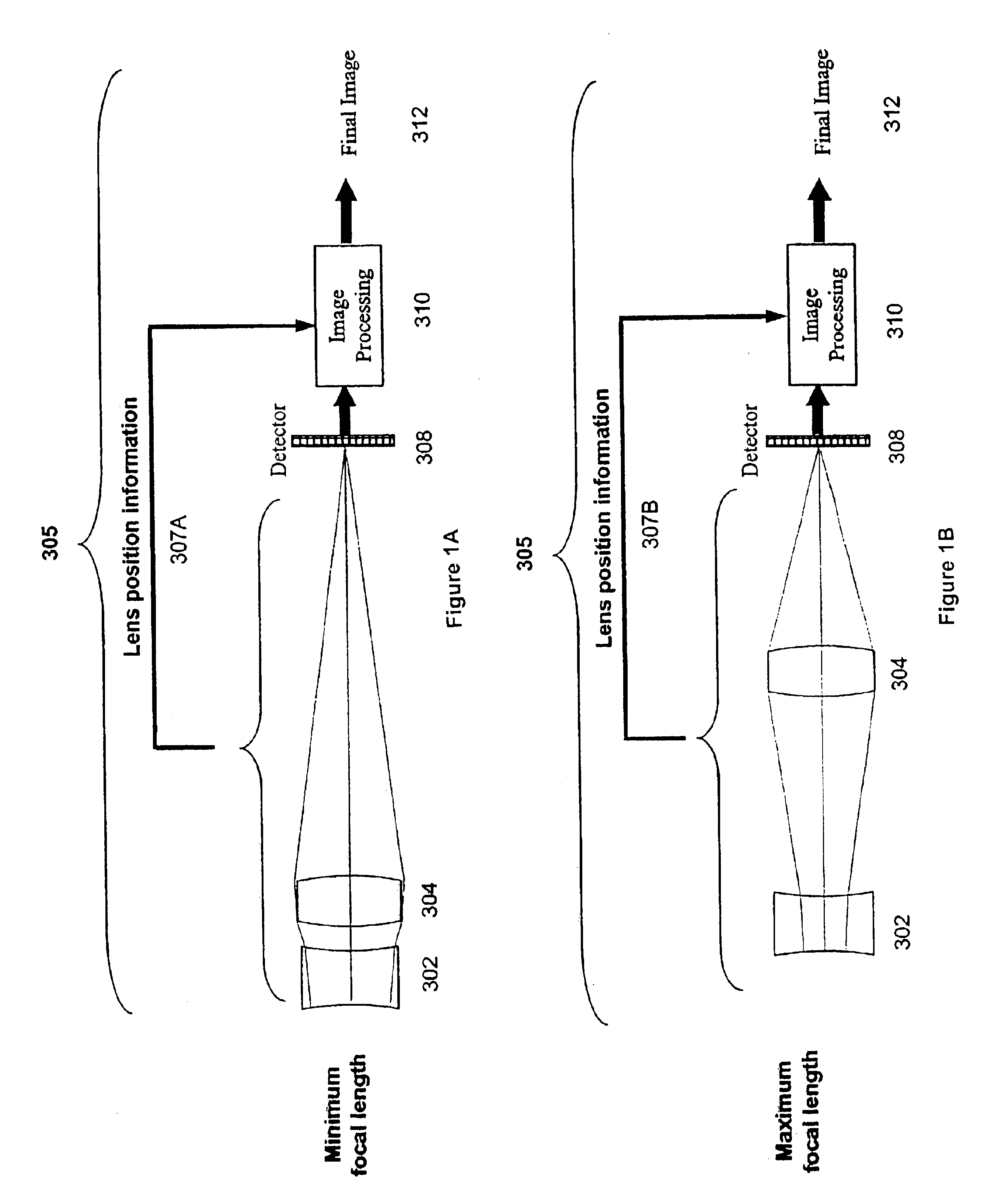
[0026]There are two primary forms of zoom lens systems that use Wavefront Coding. The first form, shown in FIG. 1A and FIG. 1B, uses as few as two lens elements 302, 304. By changing the distance between the two lens elements 302, ...


PUM


Abstract

A wide-angle zoom lens with as few as two plastic elements codes the wavefront produced by the imaging system such that the imaging system is substantially invariant to aberrations related to misfocus. Signal processing is used to decode the wavefront to form the final image. A first type of zoom lens configuration uses as few as two lens elements. In this type, image processing may be modified to take into account the positioning of the lenses.

Description

CROSS-REFERENCE TO RELATED APPLICATIONS[0001]This patent application is a continuation-in-part of commonly-owned and U.S. patent application Ser. No. 09 / 910,675, now abandoned, filed on Jul. 20, 2001 and incorporated herein by reference. This patent application is also a continuation-in-part of commonly-owned and U.S. patent application Ser. No. 09 / 070,969, filed on May 1, 1998 now abandoned and incorporated herein by reference. U.S. patent application Ser. No. 09 / 070,969 is a continuation-in-part of U.S. patent application Ser. No. 08 / 823,894, filed Mar. 17, 1997, now U.S. Pat. No. 5,748,371, issued May 5, 1998 and incorporated herein by reference. U.S. patent application Ser. No. 08 / 823,894 is a continuation of U.S. patent application Ser. No. 08 / 384,257, filed Feb. 3. 1995, now abandoned. U.S. application Ser. No. 09 / 875,435, filed Jun. 6, 2001, now U.S. Pat. No. 6,525,302, and pending U.S. application Ser. No. 09 / 875,766, filed June 6, 2001, and Ser. No. 09 / 766,325, filed Jan. 1...

Claims


Application Information

Patent Timeline
Patent Type & Authority Patents(United States)
IPC IPC(8): G02B15/00G02B27/00G02B27/46G02B5/00
CPCG02B15/173G02B15/177G02B27/46G02B27/0075G02B27/0025G02B15/143
Inventor DOWSKI, JR., EDWARD RAYMONDPRISCHEPA, INGA
Owner COLORADO UNIV OF RGT
Learn More