
Programmable limit switch with distributed intelligence

Inactive Publication Date: 2005-06-28
AMETEK INC
View PDF12 Cites 14 Cited by
  • Summary
  • Abstract
  • Description
  • Claims
  • Application Information

AI Technical Summary

Benefits of technology

[0012]The present invention is a programmable limit switch with distributed intelligence that is capable of controlling a large number of circuits simultaneously. The switch operates without performance degradation when the number of input and output circuits expands, even when operated at high speeds. The programmable limit switch (PLS) establishes a timing of events in a workpiece treatment process carried out as a workpiece traverses through a production field. The PLS includes a plurality of output channels for receiving position data where each position value of the position data represents an advance of the workpiece through the production field. The output channels are also used for producing device actuation signals, each of the plurality of output channels connectable to an output device responsive to the respective device actuation signals and located in the production field. An output controller is in each of the plurality of output channels and is individually programmable to change a state of the respective device actuation signals in response to reaching selected position values.
[0018]Various function are programmable into the plurality of output channels. For example, any number of the output controllers is programmable to change a state of a respective device actuation signal in response to a first position and to change the state again after a predetermined period of time. In addition, any number of the output controllers is programmable to change a state of a respective device actuation signal at an ON setpoint associated with a first position value and to change a state of the respective device actuation signal again at an OFF setpoint associated with a second position value, the ON and OFF setpoints defining a respective setpoint pair. Any of these standard channel outputs can be modified by programming it to add a first offset to the respective ON setpoint based upon a comparison of a base speed to an actual speed of travel determined from a sample number of position values and to add a second offset to the respective OFF setpoint based upon the comparison, providing linear speed compensation. When the actual speed of travel drops below a predetermined speed, an output controller so programmed can optionally de-energize a respective device actuation signal.
[0021]In one embodiment of the PLS, the plurality of output channels are mounted on two or more expansion circuit boards, each expansion circuit board having an expansion in port and an expansion out port through which the two or more expansion circuit boards are serially connected. This allows flexible, modular design of the PLS. If the two or more expansion circuit boards are each enclosed within a separate housing and a main programmable controller is mounted within a first one of the housings, expansion of the number of output channels controllable by the PLS is possible.
[0026]Yet another embodiment of the PLS includes a plurality of input connectors for receiving device input signals and connectable to respective input devices located within the production field, each input connector coupled to a respective output channel. Optionally, at least one of the output controllers is programmable to change a state of a respective device actuation signal at an ON setpoint associated with a first position value and to change a state of the respective device actuation signal again at an OFF setpoint associated with a second position value, the ON and OFF setpoints defining a respective setpoint pair. Many variations using the a setpoint pair are possible.
[0030]As taught herein, the PLS of the present invention allows high speed operations with minimal mechanical wear due to its electronic construction. This also allows adjustments to the settings of the switches to be performed when the PLS A is operating and easily allows multiple ON and OFF points for a single output limited only by memory and processor speed. Its modular design allows easy expansion and installation.

Problems solved by technology

Serial addressing is less common for many applications due to the problems associated with determining for which serially-connected device a signal from the central processing unit is intended.
Of course, a device controlled by the programmable limit switch, such as the glue gun described in the example, can have a constant delay from the time it receives an electrical signal to the time the desired mechanical action occurs.
The determination of what the offset should be is complicated by the fact that as the velocity of the mechanical system changes, the offset changes.
Another complication is that many mechanical devices require two offsets because the delay for activating the device is often different from the delay for deactivating the device.
This microprocessor can control many output circuits driving output devices from one position reading, but cannot operate at high speeds or with many simultaneously-controlled output circuits without a significant degradation in performance.
Further, as programmable limit switches incorporate more and more functions due to the inclusion of a more powerful microprocessor, operating such switches has become more complicated and involved, necessitating many hours to understand how to program the microprocessor to create even the simplest set of operating instructions.

Method used


Image

  • Programmable limit switch with distributed intelligence
  • Programmable limit switch with distributed intelligence
  • Programmable limit switch with distributed intelligence

Examples


Embodiment Construction

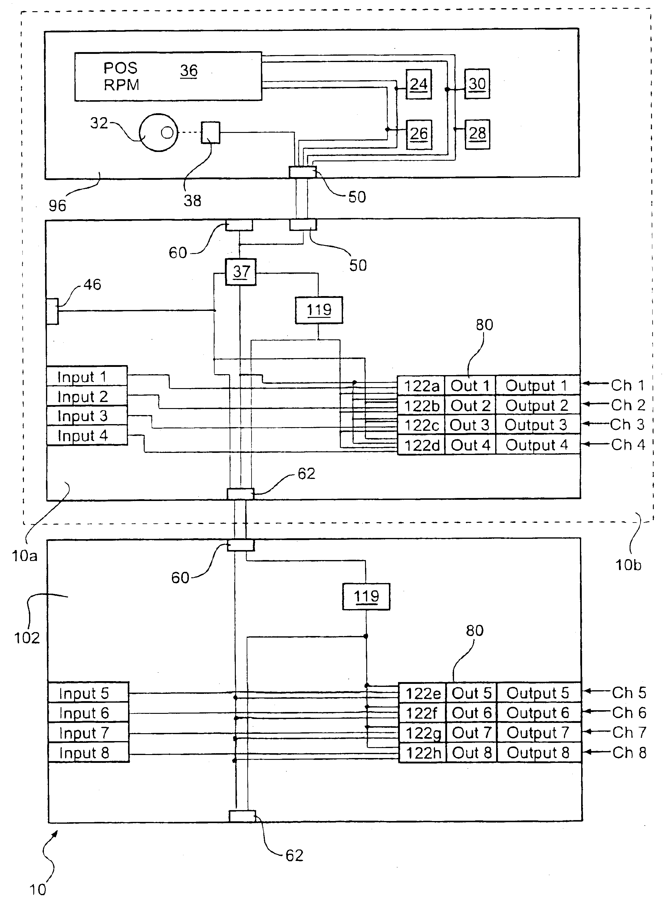
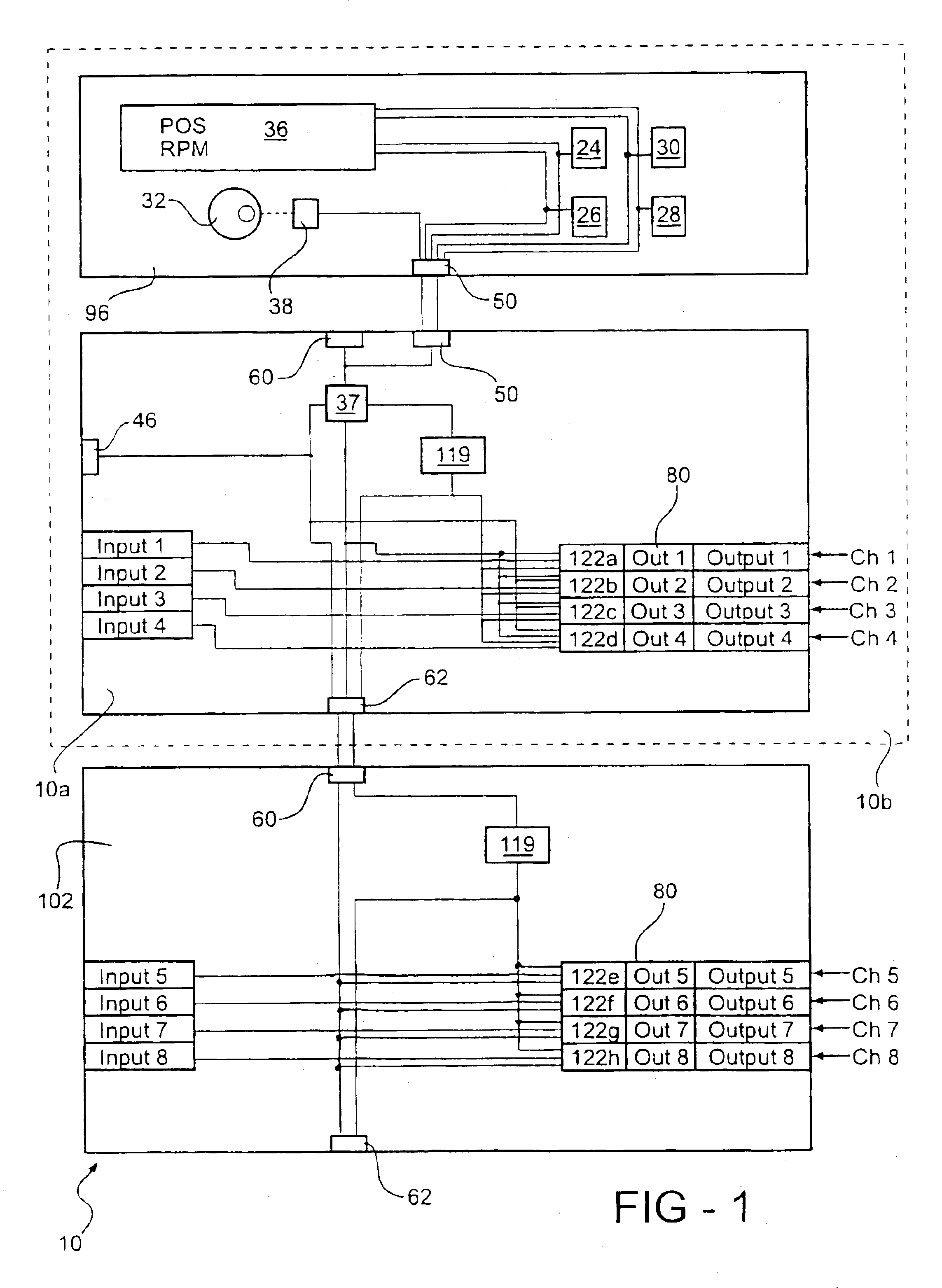
[0052]The programmable limit switch incorporating the present invention is shown and described with reference to FIGS. 1-18. FIG. 1 shows a block diagram of certain modules of the programmable limit switch (PLS) 10 incorporated into a portion of a system with eight input connectors. Inputs 1-8 internally tied to eight output circuits, or channels, Ch 1-8, respectively. The input connectors. Inputs 1-8 and output channels. Ch 1-8 are split evenly between a blind main controller 10a and an expansion module 102, which are two modules of the PLS 10. Thus, input connectors. Inputs 14 and output channels. Ch 14 are mounted on the blind main controller 10a, while input connectors. Inputs 5-8 and output channels. Ch 5-8 are mounted on the expansion module 102. Although the four input connectors and four output channels are incorporated into the embodiments shown, eight input connectors and output channels on each of the blind main controller 10a and the expansion module 102 are preferred.

[0...


PUM


Abstract

A programmable limit switch includes output channels for receiving position data, each position value of the position data representing an incremental advance of a workpiece through a production field, and for producing actuation signals. The channels are connectable to respective output devices responsive to the respective actuation signals and located in the field. Each output channel has an output controller, which is individually programmable to change the state of respective actuation signals in response to reaching selected position values. Preferably, the PLS includes input connectors coupled to a respective channel and connectable to respective input devices located within the production field. Each channel operates its own inputs and outputs according to a variety of programmed functions depending upon system conditions seen by the output controller.

Description

RELATED APPLICATIONS[0001]This invention is related to simultaneously filed, co-pending application Ser. No. 10 / 104,563 entitled “AUTOMATIC ADDRESS SELECTION METHOD,” the disclosure of which is incorporated herein in its entirety by reference.BACKGROUND OF THE INVENTION[0002]1. Field of the Invention[0003]The present invention relates to programmable limit switches.[0004]2. Description of the Related Art[0005]In a variety of applications, many devices must be addressed by a central processing unit. For certain applications, addressing the devices in parallel is common. For example, a number of memory devices in computing applications are commonly addressed in parallel by a central processing unit. This parallel addressing requires a dedicated connection from the central processing unit to each memory device. Serial addressing is less common for many applications due to the problems associated with determining for which serially-connected device a signal from the central processing u...

Claims


Application Information

Patent Timeline
IPC IPC(8): G05B11/01G05B19/042
CPCG05B19/042G05B2219/25045G05B2219/23395
Inventor PATTEE, JACKCHAMPAGNE, SHEILA F.
Owner AMETEK INC
Learn More