Method for engine condition control with turbocompressor controllable bypass

a technology of bypass and turbocompressor, which is applied in the direction of combustion engines, machines/engines, engine controllers, etc., can solve the problems of not having a closed-loop control strategy, and generally not being able to survive in such high temperatures and harsh environments for long periods of operation. , to achieve the effect of reducing cylinder oxygen content, reducing nox emissions, and reducing cylinder pressur

Inactive Publication Date: 2005-07-05
ELECTRO-MOTIVE DIESEL
View PDF15 Cites 32 Cited by
  • Summary
  • Abstract
  • Description
  • Claims
  • Application Information

AI Technical Summary

Benefits of technology

[0009]A control method of the present invention operates to continuously monitor the engine combustion (intake manifold) air density and peak firing pressure, and control the combustion air quantity supplied to the engine such that the engine will always operate under the maximum allowable peak cylinder firing pressure and / or turbine inlet temperature. Controlling the amount of charge air rather than the amount of fuel injected provides much faster dynamic response in changing the engine operating conditions without reducing the engine load or causing load swings.
[0021]The bypass system may be utilized under various engine operating conditions to reduce cylinder pressures as well as to lower cylinder oxygen content, both of which will result in the production of lower NOx emissions. The bypass of compressor air directly into the engine exhaust manifold can reduce manifold exhaust temperature and lower the NOx present in the exhaust.
[0022]The method can be used to limit peak cylinder firing pressures. It can also improve turbine life by limiting maximum turbine inlet temperatures. The method can additionally recover a large percentage of the compressor discharge energy by passing the compressed air through the turbine. Further, the reduced air flow through the engine reduces the cooling load on the charge air cooler, providing for more efficient system operation.

Problems solved by technology

However, there is apparently no closed loop control strategy existing now to monitor and control these parameters during actual engine operation.
However, it is believed that no such control strategy exists or has been practiced.
Furthermore, temperature sensors generally do not survive in such high temperatures and harsh environments for long periods of operation.
However, a method and application of a compressor bypass system for controlling other engine conditions has apparently not been proposed.

Method used


Image

  • Method for engine condition control with turbocompressor controllable bypass
  • Method for engine condition control with turbocompressor controllable bypass
  • Method for engine condition control with turbocompressor controllable bypass

Examples


Embodiment Construction

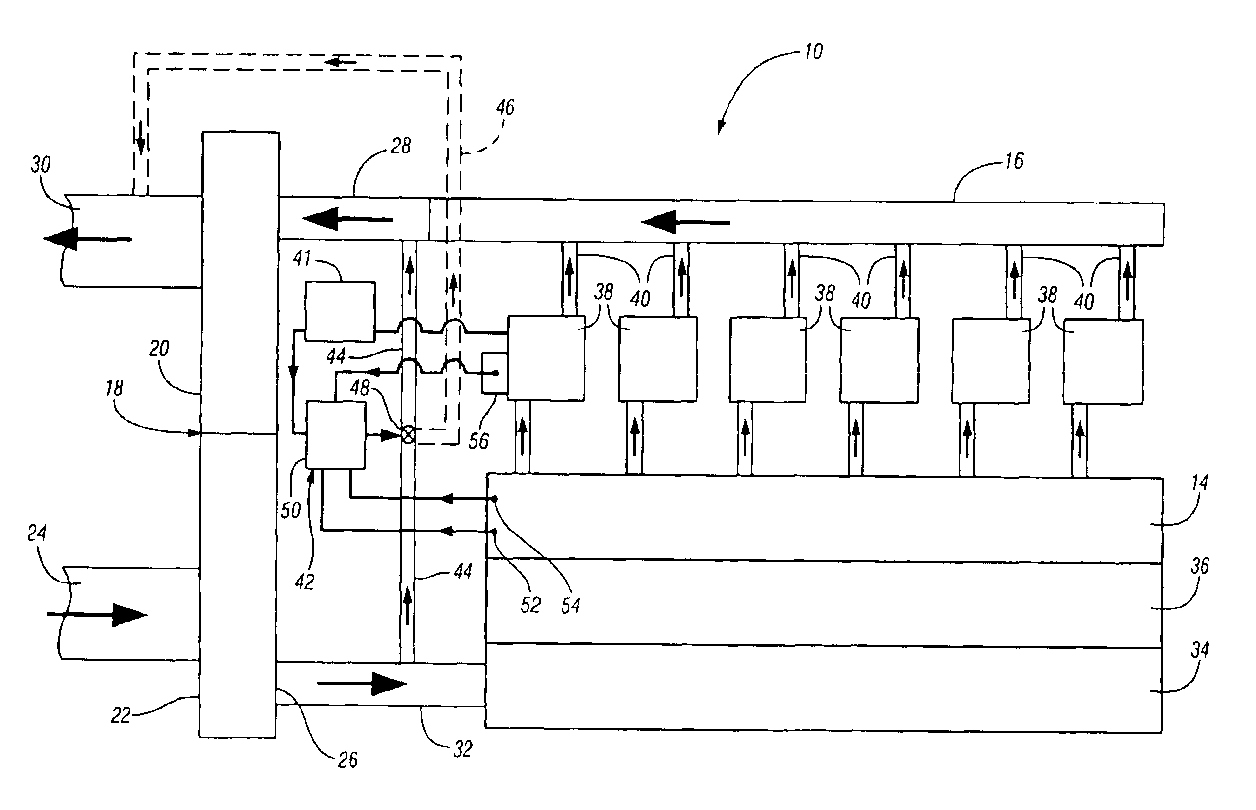
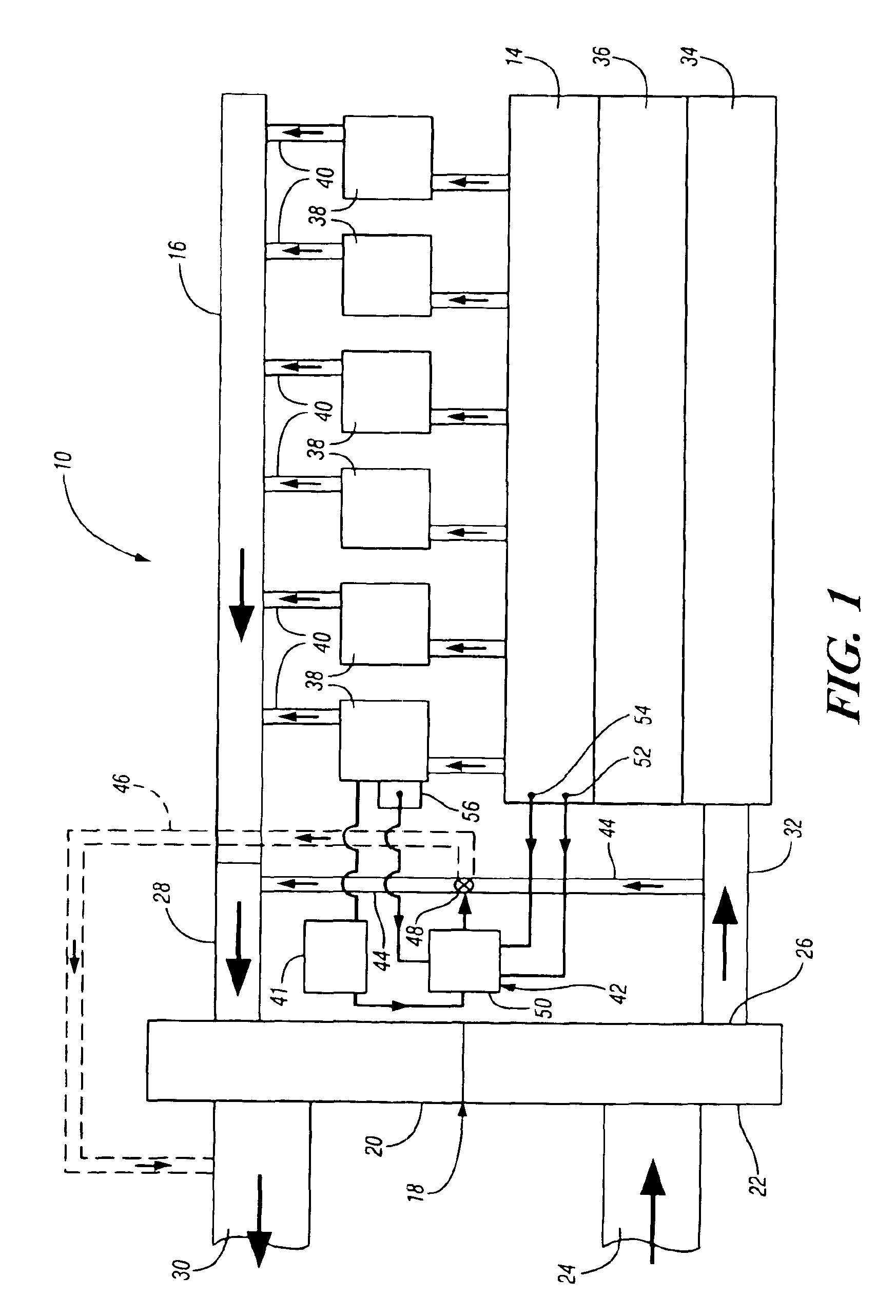
[0026]Referring now to the drawings in detail, numeral 10 generally indicates an internal combustion engine, such as a diesel engine for railroad locomotives, marine applications and other uses. Engine 10 includes a charge air inlet or manifold 14, and an exhaust outlet including an engine exhaust manifold 16. A turbocharger 18 is mounted on or adjacent to the engine and includes internally a turbine 20 driving a compressor 22.

[0027]The compressor 22 includes an ambient air inlet 24 and a compressed air outlet 26. The turbine 20 includes an exhaust gas inlet 28 and an exhaust discharge or outlet 30.

[0028]The compressor outlet 26 is conventionally connected through a duct 32 with an inlet header 34 for a charge air cooler 36. The air cooler 36 discharges to the manifold 14 which delivers cooled compressed inlet air to the engine cylinders 38. The engine cylinders discharge through one or more exhaust outlets 40 to the exhaust manifold 16, which carries the engine exhaust gas to the i...


PUM


Abstract

A system for a turbocharged internal combustion engine includes an engine having a charge inlet connected to the compressor outlet and an exhaust outlet connected to the turbine inlet for driving the turbocharger with hot exhaust gas and supplying compressed air to the engine for combustion. A bypass duct connects the compressor outlet to the turbine inlet for diverting a portion of the compressed air around the engine to the turbine inlet or exhaust. A control device selectively controls the diversion of air. An operating method for the system involves controlling peak cylinder firing pressure and / or maximum turbine inlet temperature, optionally with exhaust NOx and smoke in order to limit these variables to acceptable limits with a minimum of operational limitations.

Description

CROSS-REFERENCE TO RELATED APPLICATIONS[0001]This application is a Continuation-In-Part of U.S. patent application Ser. No. 10 / 106,093 filed Mar. 26, 2002 now ABN.TECHNICAL FIELD[0002]This invention relates to turbocharged internal combustion engines, such as diesel engines, and more particularly to a system and method for controlling peak cylinder pressures and / or exhaust emissions and providing certain operational and performance advantages.BACKGROUND OF THE INVENTION[0003]For a given engine size and hardware, the maximum allowable peak cylinder firing pressure and turbine inlet (engine exhaust gas) temperature are generally defined during the component design process to limit engine operation below these threshold values. However, there is apparently no closed loop control strategy existing now to monitor and control these parameters during actual engine operation. Limiting engine operation within the allowable (pre-defined) peak firing cylinder pressure and turbine inlet tempera...

Claims


Application Information

Patent Timeline
Patent Type & Authority Patents(United States)
IPC IPC(8): F02B37/20F02B37/16F02B37/12
CPCF02B37/16F02B37/20Y02T10/144Y02T10/12
Inventor GOTTEMOLLER, PAULPOOLA, RAMESH B.CORBA, DAVIDZAGONE, JOHN R.
Owner ELECTRO-MOTIVE DIESEL
Why Eureka
Try Eureka