
Sub-reamer for bi-center type tools

a tool and sub-reamer technology, applied in the field of drill bits, can solve the problems of high stress on drilling equipment, high torque, directional drilling control problems, etc., and achieve the effect of improving the wear characteristics of tools and enhancing the stability of boreholes

Inactive Publication Date: 2005-07-05
REEDHYCALOG LP
View PDF16 Cites 18 Cited by
  • Summary
  • Abstract
  • Description
  • Claims
  • Application Information

AI Technical Summary

Benefits of technology

[0017]The present invention has a number of advantages over the prior art. One such advantage is enhanced stability in the borehole during a variety of operating conditions. Another advantage is improved wear characteristics of the tool.
[0018]In some applications, it is required that a pilot hole be drilled with another drilling tool before the bi-center is used or in the middle of a bi-center run. Conventional bi-centers can do this only if the pilot hole is the same size as the bi-center pilot bit or smaller. If the pilot hole is larger than the bi-center pilot bit then the bi-center will produce an undersized hole (the pilot bit will not center the bi-center in the hole). In most of these applications, the pilot hole is larger than the bi-center pilot, eliminating the use of the bi-center and forcing the use of less efficient tools. Since the sub-reamer has a larger cutting diameter than the pilot bit, a bi-center with a sub-reamer can be used in a pilot hole that is equal to or smaller than the cutting diameter of the sub-reamer.

Problems solved by technology

A significant source of many drilling problems relates to drill bit and string instability.
Bit and / or string instability probably occurs much more often than is readily apparent by reference to immediately noticeable problems.
However, when such instability is severe, it places high stress on drilling equipment that includes not only drill bits but other downhole tools and the drill string in general.
Common problems caused by such instability may include, but are not limited to, excessive torque, directional drilling control problems, and coring problems.
However, this solution is usually expensive and can actually limit performance.
While this design makes the PDC cutters stronger so as to reduce cutter damage, it does not solve the primary problem of bit instability.
Thus, drill string problems, directional drilling control problems, and excessive torque problems remain.
Also, because the PDC diamond table must be ground on all of the PDC cutters, the drill bits made in this manner are more expensive and less resistant to abrasive wear as compared to the same drill bit made with standard cutters.
Bit whirl is a very complicated process that includes many types of bit movement patterns or modes of motion wherein the bit typically does not remain centered within the borehole.
The solution is based on the premise that it is impossible to design and build a perfectly balanced bit.
One drawback to this method is that for it to perform properly in the borehole, the bit forces must be the dominant force acting on the bit.
Unfortunately, there are many cases where gravity or string movements create forces larger than the designed cutting force imbalance and therefore become the dominant bit forces.
In such cases, the intentionally designed imbalance is ineffective to prevent the tool from becoming unstable and whirling in operation in the borehole.
Furthermore, penetration limiters reduce bit rate of penetration of used too extensively but do not significantly improve stability of used too sparingly.
Due to the variety of different applications, it is frequently difficult to determine to what extent penetration limiters should ve used.
While the above background has been directed to drill bits in general, more specific problems of bit instability are created in the instance of the bi-center bit.
Problems associated with the bi-center bit, however, include those of a short life due to irregular wear patterns and excessive wear, the creation of a smaller than expected hole size and overall poor directional characteristics.
Secondly, the geometry of a bi-center bit limits the number of positions for penetration limiters on one side of the bit.
Placing more penetration limiters on one side of the bit can cause a force imbalance that makes the bit less stable.
The disadvantage of this is that it requires that the pilot bit produce a true size hole.
As a result of these and other proposed problems, the bi-center bit has yet to realize its potential as a reliable alternative to undereaming.

Method used


Image

  • Sub-reamer for bi-center type tools
  • Sub-reamer for bi-center type tools
  • Sub-reamer for bi-center type tools

Examples


first embodiment

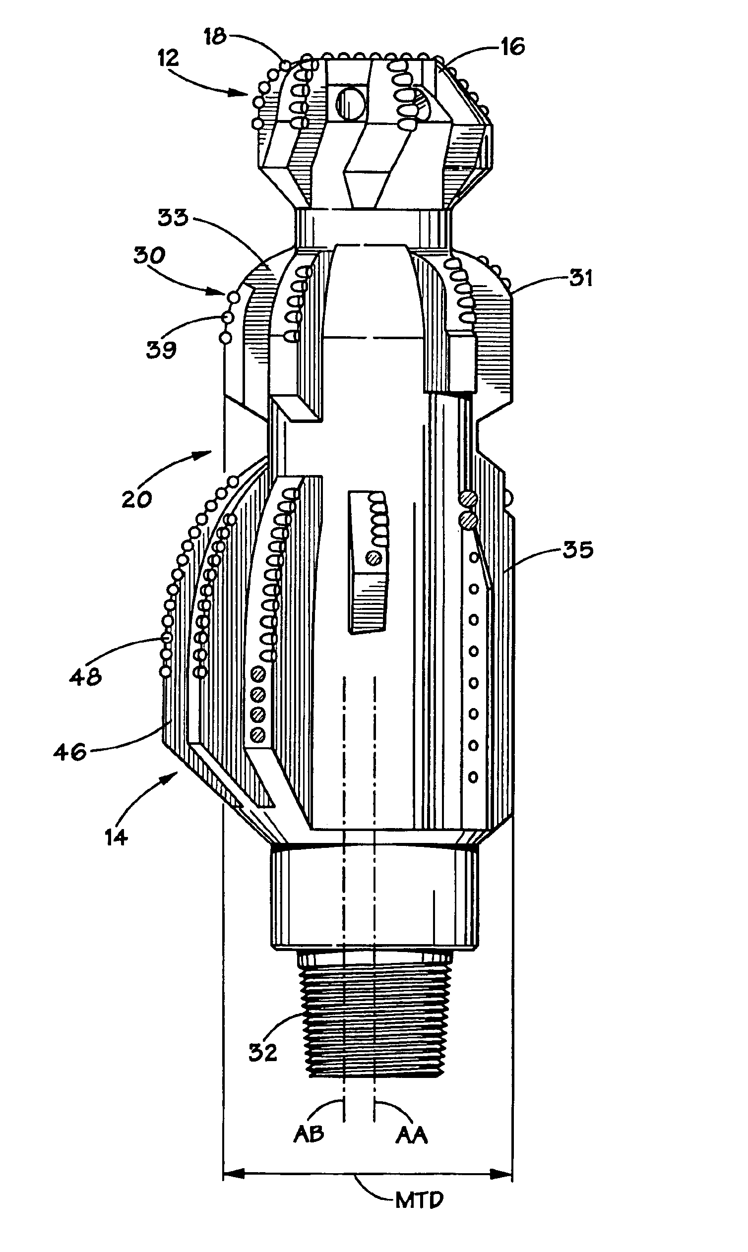
[0040]the present invention may been seen by reference to FIGS. 5-6. In these Figures there is illustrated a bi-center tool 100 which includes a pilot bit section 102 and a reamer section 104 which are oriented about the tool in the fashion described above with respect to the general embodiment. The tool 100 defines a rotational axis “AA” and a maximum tool diameter “MTD”, as also defined above in relation to the general embodiment.

[0041]A sub-reamer 108 is positioned intermediate of the pilot 102 and reamer 104 sections. In this embodiment, the sub-reamer 108 is provided with a plurality of cutting blades 110 which define endpoints 111 which extend to a distance less than or equal to the maximum tool diameter “MTD”, as measured from the rotational axis “AA”. These cutting blades 110 are radially distributed in an arc greater than or equal to 180 degrees about the sub-reamer 180. In a preferred embodiment, endpoints which extend the same distance from “AA” and generally extend about...

second embodiment

[0042]the invention may be seen by reference to FIGS. 7-8. In these Figures is illustrated a bi-center tool 140 which includes a pilot section 142, a reamer section 144 and a sub-reamer section 150 whose respective orientation has been described above. Tool 140 defines a rotational axis “AA” and a pass-through axis “AB”. The rotation of the tool about the pass-through axis “AB” defines a pass-through diameter “PTD”. The maximum tool diameter “MTD” and reamer drill diameter “RDD,” as defined above, are also illustrated.

[0043]In this embodiment, the cutting blades on the reamer section 144 describe an arc which further defines a midpoint “Q.” This midpoint “Q” can be determined by bisecting the linear distance between the endpoint 161 on the leading edge 160 of the first blade 162 and the endpoint 163 on the trailing edge 166 of the last blade 168, as illustrated.

[0044]Consistent with previous embodiments, the sub-reamer section 150 is provided with a number of cutting blades 152, eac...

third embodiment

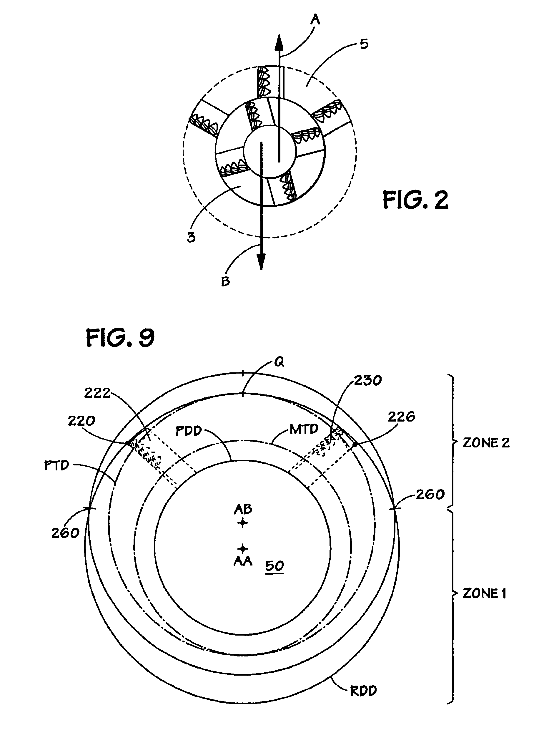
[0048]the invention is illustrated at FIGS. 9-10 in which is disclosed a bi-center downhole tool 200 which includes a pilot section 202, reamer section 204 and sub-reamer section 212, as described above in relation to the prior embodiments. Tool 200 defines a rotational axis “AA” and a pass-through axis “AB”, as illustrated in both FIGS. 9-10. Consistent with prior embodiments, the tool defines a maximum tool diameter as indicated at “MTD”. The rotation of the tool about the pass-through axis “AB” defines a pass-through diameter “PTD”. The rotation of the reamer section 204 about the rotational axis defines a reamer drill diameter “RDD”. (See FIG. 9).

[0049]The cutting blades or upsets 206 disposed on the reamer section 204 describe an arc which further defines a midpoint “Q”. In this embodiment, this midpoint “Q” is also determined by bisecting the linear distance between the endpoint of the leading edge 220 of the first blade 222 and the endpoint of the trailing edge 226 of the las...


PUM


Abstract

An improved bi-center with improved directional stability and wear resistance is disclosed, said bit optimally utilizing a plurality of shaped PDC cutting elements selectively situated about the cutting surfaces of the pilot and the reamer to produce a minimal force imbalance, where further said pilot bit and the reamer are force balanced to further reduce imbalance in the operation of the tool.

Description

BACKGROUND OF THE INVENTION[0001]1. Field of the Invention[0002]The present invention generally relates to drill bits useful for drilling oil, gas and water wells and methods for manufacturing such bits. More specifically, the present invention relates to a bi-center bit or two-piece bi-center bit which includes a sub-reamer section to aid in enhancing stability of the tool when rotated in the borehole.[0003]2. Description of the Prior Art[0004]A significant source of many drilling problems relates to drill bit and string instability. Bit and / or string instability probably occurs much more often than is readily apparent by reference to immediately noticeable problems. However, when such instability is severe, it places high stress on drilling equipment that includes not only drill bits but other downhole tools and the drill string in general. Common problems caused by such instability may include, but are not limited to, excessive torque, directional drilling control problems, and c...

Claims


Application Information

Patent Timeline
IPC IPC(8): E21B10/00E21B10/26E21B10/42E21B10/43
CPCE21B10/26E21B10/43E21B10/265
Inventor FIELDERSILVA, ROGERIO H.
Owner REEDHYCALOG LP
Learn More