

High-power well logging method and apparatus
- Summary
- Abstract
- Description
- Claims
- Application Information
AI Technical Summary
Benefits of technology
Problems solved by technology
Method used
Image

Examples
Embodiment Construction
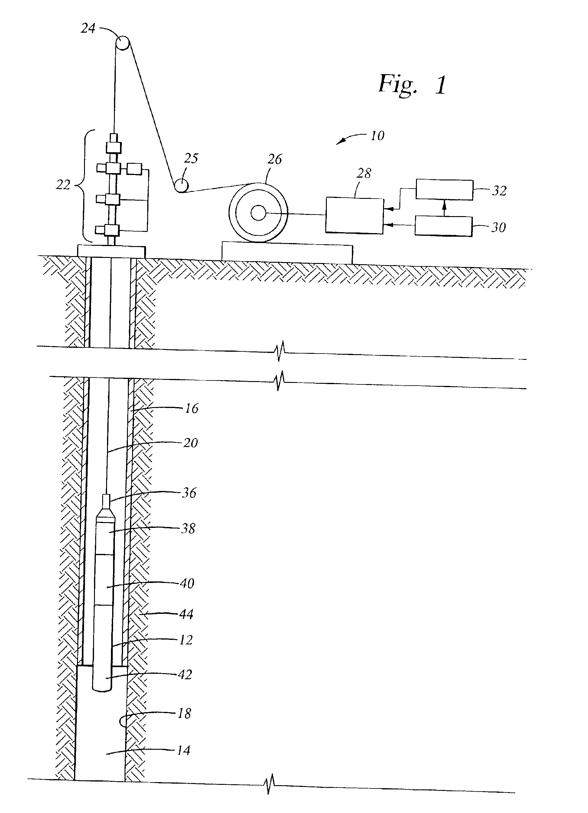
[0022]Referring initially to FIG. 1, the well logging system 10 of the present invention includes a well logging tool 12 to be lowered into a borehole 14 suspended on a cable 20. The borehole 14 may be cased with concentric casing 16 or be an open borehole such as at 18. The cable 20 extends from the tool 12 up through wellhead 22 and around a first sheave 24 and a second sheave 25 to a rotatable spool 26 for raising and lowering the cable 20 and tool 12.
[0023]The conductors in cable 20 are typically connected to a transceiver 28. In an exemplary embodiment, the conductors in cable 20 are each connected to a corresponding electrically conductive slip ring (not shown) on the spool axle. The conductive slip rings transfer electrical currents from the cable that rotates with the spool to corresponding electrically conductive brushes “riding” on the slip rings. The brushes are then coupled to the transceiver 28. In this manner, signals are transferred from the rotating spool to the stat...
PUM
 Abstract
Description
Claims
Application Information