Combined radiation therapy and imaging system and method

a radiation therapy and imaging system technology, applied in the field of combined radiation therapy and imaging system and method, can solve the problems of x-ray imaging source and image forming system, less than optimal image quality, and relatively expensive standard diagnostic ct scanners

Inactive Publication Date: 2005-07-05
ANLOGIC CORP (US)
View PDF10 Cites 193 Cited by
  • Summary
  • Abstract
  • Description
  • Claims
  • Application Information

AI Technical Summary

Benefits of technology

[0022]wherein the radiation therapy subsystem provides the beam of the therapeutic X-rays in a direction which is in a plane that is substantially fixed relative to the slice plane of the CT imaging system so that the targeted region can be imaged, and exposed to the beam of therapeutic X-rays without the necessity of moving the patient.
[0023]Preferably the radiation therapy subsystem provides the therapeutic X-rays in a direction within a plane that is substantially coplanar with the slice plane of the CT imaging system so that the targeted region can be imaged, and exposed to the therapeutic X-rays without the necessity of moving the patient.
[0025]providing the therapeutic X-rays in a direction which is substantially fixed relative to a slice plane of the CT imaging subsystem so that the targeted region can be imaged during a planning phase, and imaged and exposed to the therapeutic X-rays during the treatment phase without the necessity of moving the patient.
[0026]In the preferred method the therapeutic beam provides the therapeutic X-rays in a direction within a plane that is substantially fixed relative to a slice plane of the CT imaging subsystem so that the targeted region can be imaged during a planning phase, and imaged and exposed to the therapeutic X-rays during the treatment phase without the necessity of moving the patient.
[0030]wherein the beam of the therapeutic X-rays is delivered in a direction which is in a plane that is substantially fixed relative to the slice plane so that the targeted region can be imaged, and exposed to the beam of therapeutic X-rays without the necessity of moving the patient.

Problems solved by technology

However, in the prior art the relative position of organs within the body during a diagnostic CT scan are not the same as when a patient is placed on a flat couch of the radiation therapy machine.
Further, standard diagnostic CT scanners tend to be relatively expensive.
In existing simulators, because the geometry of the simulator attempts to very closely simulate that of the radiotherapy machine, the X-ray imaging source and image forming system are limited to a configuration which is less than optimal for the quality of the image.
This prior art system employing the television camera produces a noisy image of marginal value in simulation and planning.
However, from prior CT imaging experience, it is believed that the use of video camera signals based on data off the IIT was one of the major limiting features in these designs.
Compared to the IIT, conventional video cameras have horizontal spatial resolution that can produce images with adequate resolution, but their intensity output is both limited and nonlinear.
Conventional solid state video cameras have good linearity, spatially and in intensity, but their signal dynamic range is also limited.
The major problem with simulators is that once the target region is determined for the patient with the simulator, the patient is positioned at some later time in a separate radiotherapy machine for subsequent treatment.
Even the slightest error in positioning the patient relative to the therapeutic high-energy beam of the radiation therapy machine, or movement of the patient while being treated, can displace the target region such that when the therapeutic radiation beam is delivered, it unnecessarily exposes healthy tissue, and partially or completely misses the target region.

Method used


Image

  • Combined radiation therapy and imaging system and method
  • Combined radiation therapy and imaging system and method
  • Combined radiation therapy and imaging system and method

Examples


Embodiment Construction

[0035]In general, the system combines a CT X-ray imaging system for providing the functionality of the simulator, and a high energy radiotherapy machine. The X-ray imaging system can be used for both planning treatment and subsequently used during treatment. The X-ray imaging system is preferably a high resolution imaging system that can create images using CT reconstruction techniques, as well as stationary and scout views. Preferably, the stationary and scout views can be stereoscopic views for determining the position of the target region relative to and / or within a region of interest.

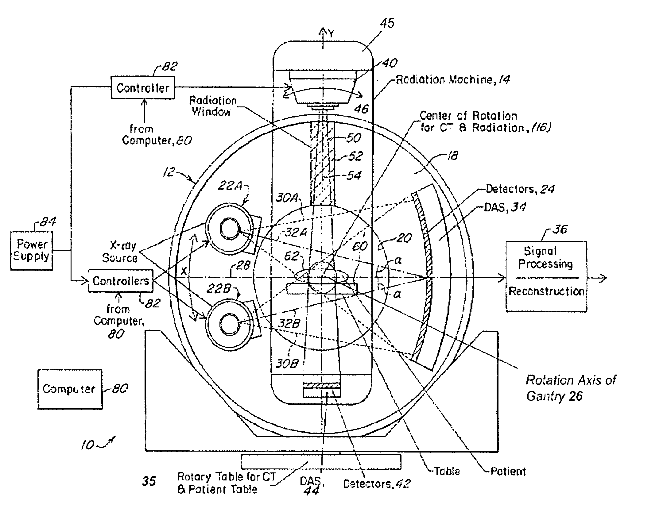
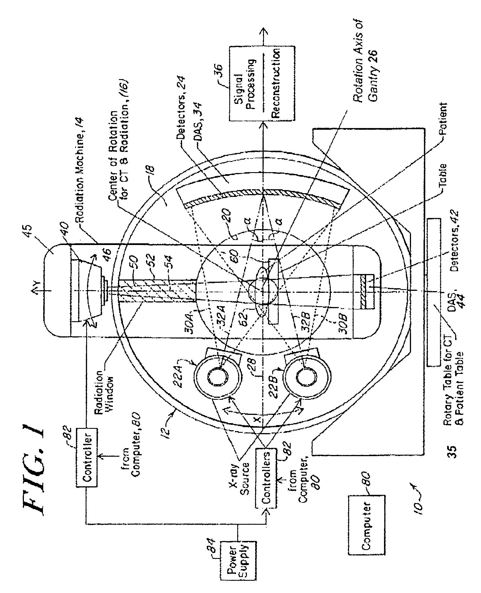
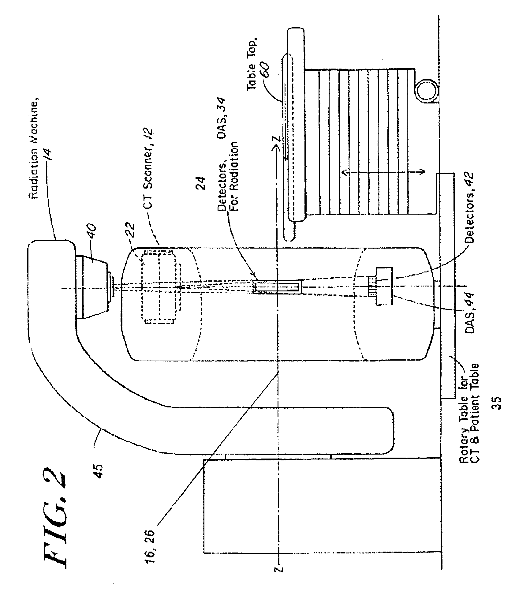
[0036]The preferred system is shown in FIGS. 1 and 2. In the system 10, the CT imaging subsystem 12, and the therapy radiation subsystem 14 are mounted for rotation about the same isocenter 16.

[0037]The imaging system 12 includes a rotatable gantry 18 having a patient aperture 20. A pair of X-ray sources 22A and 22B (or moving electron beam source) and a detector array 24 are fixedly mounted on the ...


PUM


Abstract

A method of and system for locating a targeted region in a patient uses a CT imaging subsystem and a radiotherapy subsystem arranged so the targeted region can be imaged with the imaging system and treated with a beam of therapeutic X-ray radiation using a radiotherapy subsystem. The beam of therapeutic X-rays is in a plane that is substantially fixed relative to, and preferably coplanar with, a slice plane of the CT imaging subsystem so that the targeted region can be imaged during a planning phase, and imaged and exposed to the therapeutic X-rays during the treatment phase without the necessity of moving the patient.

Description

CROSS REFERENCE TO RELATED APPLICATIONS[0001]This application is based on a provisional application, U.S. Ser. No. 60 / 311,240 filed Aug. 9, 2001.REFERENCED PRIOR ART[0002]U.S. Pat. No. 6,104,778, (Murad), X-ray Treatment and Apparatus; U.S. Pat. No. 5,692,507, (Seppi et al.) Computer Tomography Apparatus Using Image Intensifier Detector.BACKGROUND[0003]This disclosure relates to a system for and method of delivering radiotherapy using a x-ray beam for treatment. More particularly, this disclosure relates to a system for and method of determining the location of a particular target region within the body by using imaging techniques that help insure concentrated, high energy radiation is delivered only to the target region, and delivering the radiation so that it is concentrated only on the target region irrespective of patient movement during treatment.[0004]In radiotherapy, for example as practiced in x-ray oncology, it is essential to deliver a precise amount of radiation, or dose,...

Claims


Application Information

Patent Timeline
Patent Type & Authority Patents(United States)
IPC IPC(8): A61B6/02A61N5/10A61B6/03
CPCA61B6/022A61B6/032A61B6/4014A61B6/482A61N5/1049A61N5/103A61N2005/1054A61N2005/1061
Inventor BAILEY, ERIC M.TYBINKOWSKI, ANDREW P.HAROOTIAN, JR., GEORGENEMIROVSKY, LIDIA
Owner ANLOGIC CORP (US)
Why Eureka
Try Eureka