
System consisting of a microphone and a preamplifier

Inactive Publication Date: 2005-07-05
SONION NEDERLAND
View PDF19 Cites 116 Cited by
  • Summary
  • Abstract
  • Description
  • Claims
  • Application Information

AI Technical Summary

Benefits of technology

[0010]An important advantage of the use of an electronic filter for cutting off high frequencies is that it affords greater freedom in positioning the resonance peak in the response characteristic of the microphone and also that this position does not need to be as accurate. This resonance peak can be influenced by varying the stiffness of the diaphragm and / or varying the distance between the backplate and the diaphragm. In microphones without electronic filtering, the resonance peak is placed in the audible frequency range to enable attenuating noise of frequencies above that of the resonance peak. In the use of the invention, the resonance peak can be placed outside the audible range and with the aid of the electronic filter a virtually flat frequency response in the desired audible frequency range can be realized. Further, it is no longer necessary to provide elements in the snout to influence the frequency behavior. Through all these measures, the microphone capsule can be fabricated more cheaply, because fewer parts and / or manufacturing steps are needed, and the tolerances for the positions or dimensioning of a number of parts of the microphone do not need to be as accurate.

Problems solved by technology

This has as a consequence, however, that the low-frequency filtering, which is usually obtained with the pressure equalization hole, is also lost.
Low frequencies are not of importance for the audibility of speech and can, if they are not suppressed, lead to overloading of the hearing aid.

Method used


Image

  • System consisting of a microphone and a preamplifier
  • System consisting of a microphone and a preamplifier
  • System consisting of a microphone and a preamplifier

Examples


first embodiment

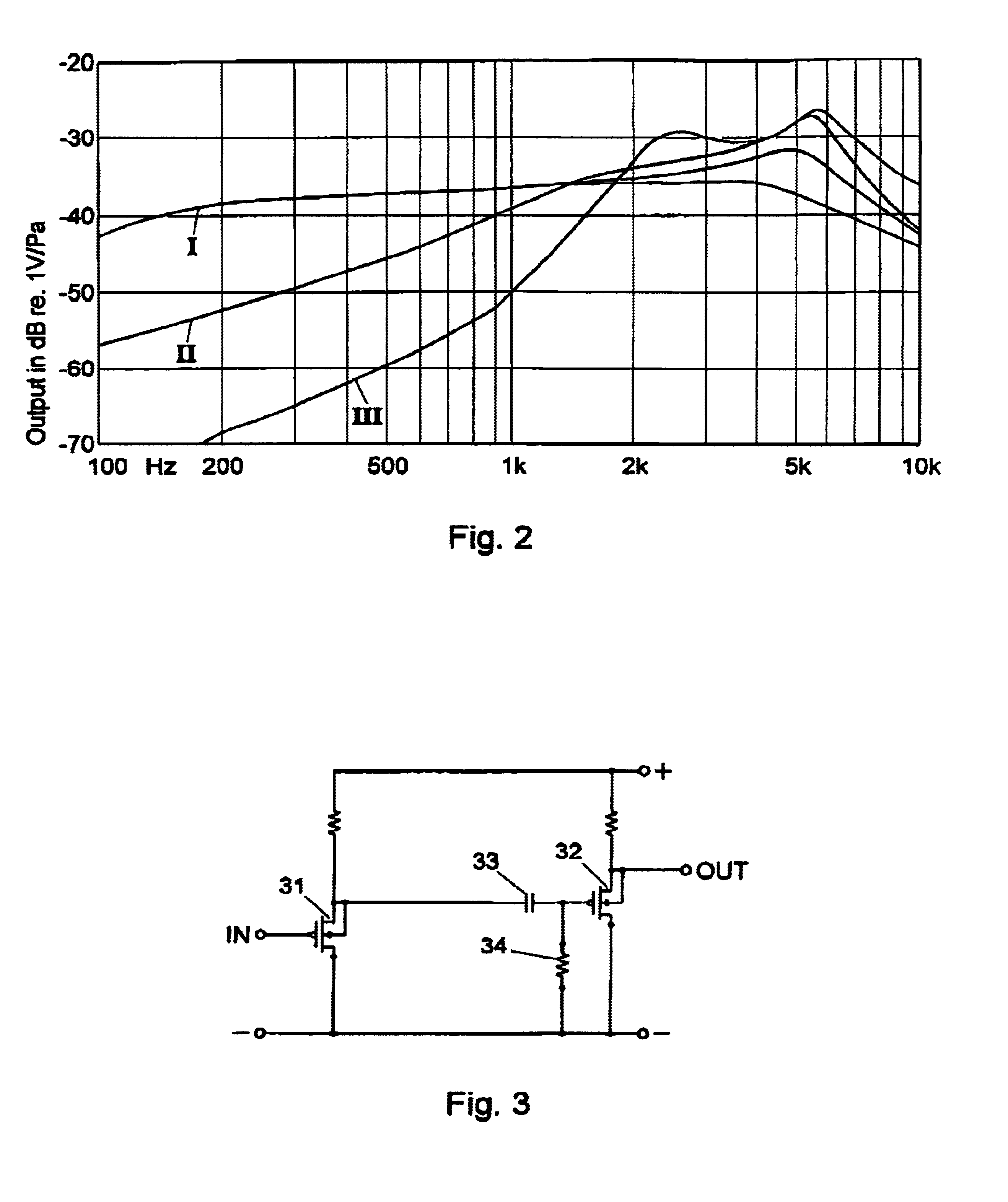
[0022]FIG. 3 schematically shows a preamplifier which can be used in the system according to the invention. The amplifier is built up around two MOS-FETs 31 and 32, which are fabricated in CMOS technique, which makes it possible to give the MOS-FET 31 an input resistance of a few TeraOhms and an input capacitance of only 1.6 pF. Other input elements having a high input impedance are also applicable, of course, and it is also possible to include the two stages of the amplifier in different techniques and even in different integrated circuits. The high-pass filter is realized by the capacitor 33 and the resistor 34 at the input of MOS-FET 32. With these components, the desired low-frequency crossover point can be fixed very easily, because they can be manufactured accurately in IC technique. The value of the capacitor 33 in practice amounts to a few hundreds of pF and the value of the resistor 34 a few MΩ. At the output of MOS-FET 32, the amplified microphone signal is available for f...

second embodiment

[0024]FIG. 4a shows the circuit according to FIG. 3, in which now, a simple variant of a low-pass filter 35 in the form of a capacitor 36 is arranged.

[0025]FIG. 4b shows more schematically that the low-pass filter 35 can be integrated into the amplifier proper or outside thereof, accommodated in the microphone housing or not. Further, the filter can be externally settable via 37, both as regards cut-off frequency and quality factor. Setting can be done manually, or the filter, if it is suited therefor, can be programmed by means of a serial or parallel interface. Various solutions to that end are well known to those skilled in the art of electronics.

[0026]Naturally, the variants of the first and second embodiment of the invention can be very well combined with each other to realize a microphone with a fully electronically settable frequency characteristic.


PUM


Abstract

A system, more particularly a hearing aid, consisting of a microphone and a preamplifier, wherein the microphone comprises a housing having therein an opening to the surroundings, a diaphragm and a backplate, while the amplifier is coupled to the system consisting of the diaphragm and the backplate and has a field effect transistor as input element. In the housing, in a space which is bounded by, on the one hand, the diaphragm and, on the other, the housing wall, and which does not comprise the opening to the surroundings, a pressure equalization opening is present, which has a diameter such that in the audible audiospectrum it does not make an essential contribution to the suppression of low frequencies. In the input stage of the amplifier, at the output of the field effect transistor, a low-pass filter or a high-pass filter or a combination thereof is arranged. Through this measure, the frequency characteristic can be optimally influenced to suppress noise.

Description

BACKGROUND OF THE INVENTION[0001]1. Field of the Invention[0002]This invention relates to a system consisting of a microphone and a preamplifier, wherein the microphone comprises a housing having therein an opening to the surroundings, a diaphragm and a backplate, while the amplifier is coupled to the system consisting of the diaphragm and the backplate and has a field effect transistor as input element.[0003]2. Description of the Prior Art[0004]The microphone is more particularly the microphone of a hearing aid. Such microphones and the associated preamplifiers (also hereinafter referred to as amplifiers) have been miniaturized further and further over the last years, so that, for instance, they can be accommodated inside, instead of outside, the ear, or even in the auditory duct. Accordingly as a microphone becomes smaller, its capacitance is generally lower. Since the noise produced by an amplifier is inversely proportional to the capacitance at the input thereof, such miniaturiz...

Claims


Application Information

Patent Timeline
IPC IPC(8): H04R19/00H04R19/01H04R1/22H04R25/00H03F3/185
CPCH04R19/016H04R1/222H04R25/604
Inventor VAN HALTEREN, AART ZEGERFURST, CLAUS ERDMANN
Owner SONION NEDERLAND
Learn More