
Prestressed composite truss girder and construction method of the same

Inactive Publication Date: 2005-07-12
WON DAE YON
View PDF23 Cites 23 Cited by
  • Summary
  • Abstract
  • Description
  • Claims
  • Application Information

AI Technical Summary

Benefits of technology

[0016]It is an object of the present invention is to provide a prestressed composite truss girder which could extend span length more than 70 m based on simply supported structure system, could efficiently resist the tensile stresses generated by external loads including dead weight, could maximize the efficiency of material use, could be applied to arbitrary-type curved structure, and could cut short the construction cost more drastically than that of the conventional composite girders.
[0020]Thus, the present invention has features in that the span length based on simply supported structure system could be extended to more than 70 m, and external loads including dead weight could efficiently be managed, and the efficiency of material use could be maximized. Also, the present invention could be applied to any shape of the structure and could cut short the construction cost considerably.

Problems solved by technology

However, the steel composite girder also has disadvantages in that the material cost is high, noise and vibration by moving loads are heavy, and maintenance and repairing cost take so much.
From this reason, the spaces under the girder often cause problems, and the economical efficiency is remarkably lowered because the amount of steel used increases extremely.
As a result, it causes extraordinary increase of the construction cost compared to the simply supported structure, and the serviceability and the durability of the composite girder will be deteriorated by water leakage caused from the crack of the slab concrete.
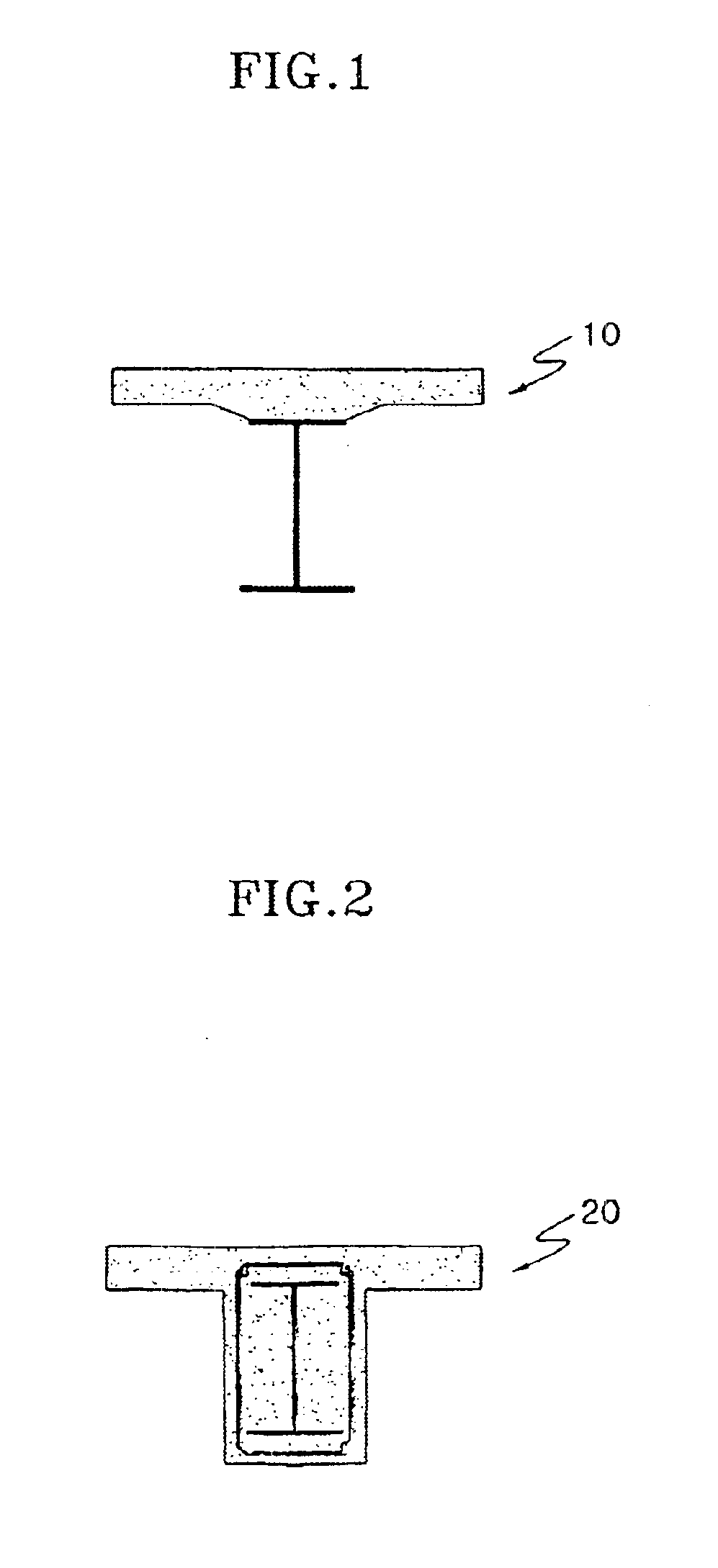
But, the SRC composite girder is more expensive than the reinforced concrete structure due to filled-in steel beam, and-the structural and economical efficiency are suddenly decreased when the span is longer than 30 m because the dead weight of the structure increase rapidly.
But, the Preflex composite girder has disadvantages in that huge equipment is required to manufacture the Preflex beam, and its construction is more complicated than that of the Steel composite girder or the SRC composite girder, and the economical efficiency is low.
Further, Preflex composite girder has structural defects in that the crack of encasing concrete may occur because the prestress introduced to the encasing concrete could be drastically decreased by the creep and shrinkage of concrete, as a result, the encasing concrete is on cracking state under working loads.
Moreover, if the span length is longer than 50 m, there is a buckling problem of steel beam when introducing preflexing load, and the economical efficiency is remarkably decreased because the amount of steel used and the construction cost for manufacturing the beam itself sharply increases.
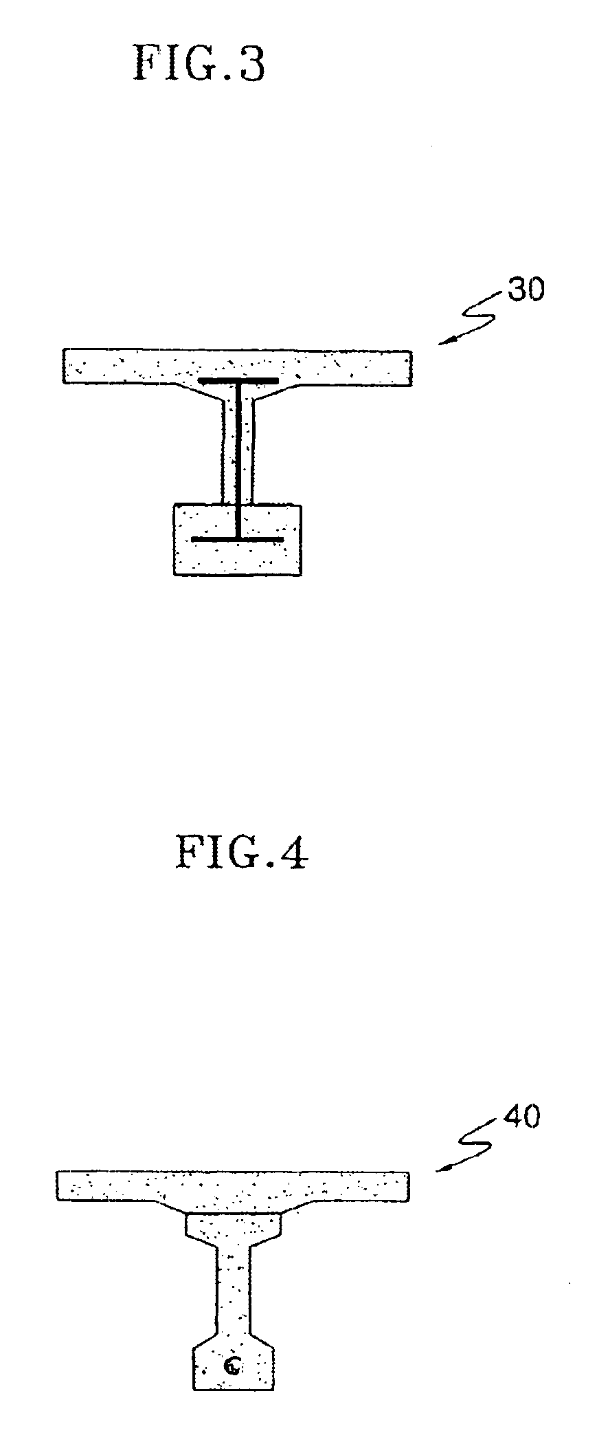
But, the PCS composite girder has disadvantages in that its dead weight is heavy, and the construction process is complicated, and the quality control for concrete is difficult.
However, the tensile stress increases rapidly due to it's heavy dead weight as the span length increases, so the more the prestressing should be introduced, and the intensity of the introduced prestress is limited by the geometric properties because the total stress at upper fiber of the cross-section exceeds the allowable tensile stress when the prestress is large.
As a result from above facts, sufficient prestress couldn't be introduced to the lower fiber of cross-section, so the beam having large stiffness to resist the tensile stress generated by dead weight of the beam and by live load, namely the high beam is required, however, this causes increase of the dead weight of the beam.
Further, the PSC composite girder has problem in that huge equipment is required for transportation and construction because lifting of the precast beam using general sized crane is impossible due to the dead weight when the span length is larger than 30 m.
Moreover, the beams used for the conventional composite girder is accompanied with many difficulties for manufacturing a certain curved structure of the plane or of the cross-section because all of them are unified solid cross-sectional structure.
Of course, it is possible that manufacturing the member having curved structure for the steel beam, but it is not competitive compared with the member having the other structural type because of steep increment of manufacturing cost and abrupt descent of construction efficiency due to it.
That is, an expensive steel or concrete box-type girder is more commonly used when the object structure is a curved bridge or curved structure that could not be corresponded with a straight-line type beam than open-type composite girder.

Method used


Image

  • Prestressed composite truss girder and construction method of the same
  • Prestressed composite truss girder and construction method of the same
  • Prestressed composite truss girder and construction method of the same

Examples


embodiment

[0043]Hereinafter, the present invention will be described in detail with reference to the preferred embodiments. But, those skilled in the art will appreciate that various modifications and substitutions can be made therein without departing from the spirit and scope of the present invention as set forth in the appended claims. The embodiments of the present invention are provided for illustrating the present invention more completely to those skilled in the art.

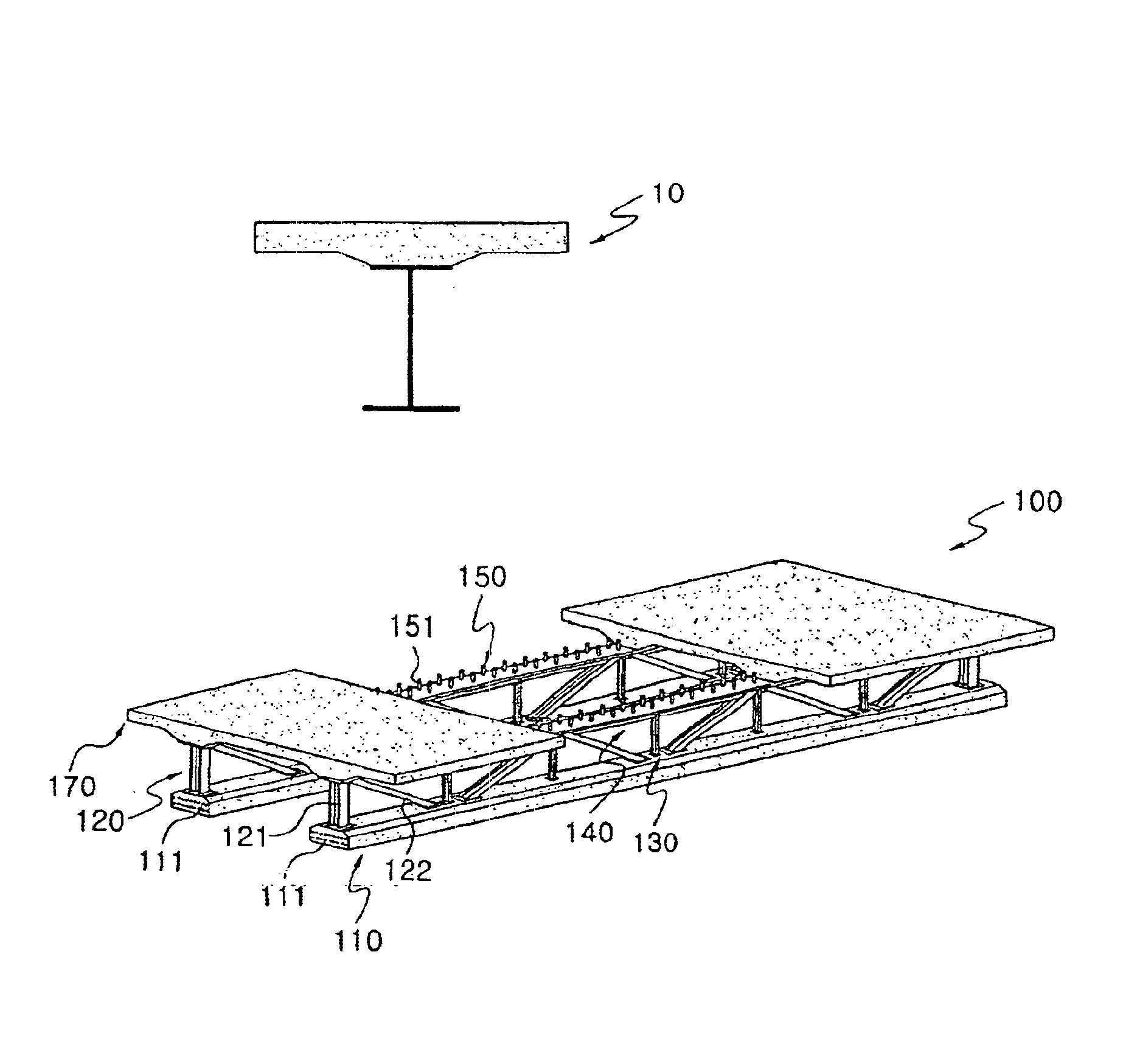
[0044]FIG. 5 is a perspective view representing the structure of a prestressed composite truss girder according to the 1st preferred embodiment of the present invention.

[0045]Referring to FIG. 5, a prestressed composite truss girder (100) according to the 1st preferred embodiment of the present invention has truss structure whereon the concrete slab(170) is composed, and comprises; a lower-chord member (110) composed of prestressed concrete wherein prestress is introduced to resist against tensile stress generated when bein...


PUM


Abstract

The present invention relates to prestressed composite truss girder and construction method of the same. The prestressed composite truss girder of the present invention comprises a concrete bottom plate having structure of composite truss; a lower-chord member being composed of prestressed concrete wherein prestress is induced to resist against the elongation strength generated when composing and not composing and to reduce the droop occurred at the state of composition and having perpendicular and horizontal cross-section of certain shape and certain length; web members wherein vertical chords and diagnal chords composed of rolled steel to upper plate of said lower-chord member; and upper-chord member combined with said web members along the longitudinal direction of said lower-chord member to resist against the compressive force generated before said concrete bottom plate being composed.

Description

BACKGROUND OF THE INVENTION[0001](a) Field of the Invention[0002]The present invention relates to a prestressed composite truss girder and construction method of the same. More particularly, it relates to a prestressed composite truss girder made by combining lower-chord member composed of prestressed concrete structure with web member composed of rolled steel and upper-chord member composed of structural steel plate, and to construction method of the same.[0003](b) Description of the Related Art[0004]Generally, the composite girders are composed of precast beam which is manufactured beforehand at a factory or a manufactory and slab concrete combined with said beam, and the bending stress and the shear stress occur when they are subjected to the external loads. In such composite girders, concrete that has strong resistance against compression is used for slab corresponding to the compression region, and steel or prestressed concrete that are highly resistant against tensile and shea...

Claims


Application Information

Patent Timeline
IPC IPC(8): E01D2/00E01D2/02E01D6/00E01D6/02E01D1/00E01D2/04E01D4/00E04C3/26E04C3/293
CPCE01D2/02E01D6/00E01D6/02E01D2101/285
Inventor WON, DAE YON
Owner WON DAE YON
Learn More