Screen cylinder and method

a technology of screen cylinder and cylinder head, which is applied in the direction of moving filter element filter, separation process, filtration separation, etc., can solve the problems of screen plate premature failure, time-consuming, labor-intensive, screen plate cracking, etc., and achieves the effect of less cross section, more wear resistance, and compact structur

Inactive Publication Date: 2005-07-12
KADANT BLACK CLAWSON LLC
View PDF110 Cites 44 Cited by
  • Summary
  • Abstract
  • Description
  • Claims
  • Application Information

AI Technical Summary

Benefits of technology

[0011]The frame has a sidewall of a solid material, such as a sheet of metal or the like, that is of perforate construction to permit flow of stock therethrough. In one preferred embodiment, the frame has triangularly shaped flow windows that enable the frame to be constructed with increased flow area that preferably encompasses at least 50% of total frame surface area while still being strong, tough, and resistant to stress cycling. One preferred arrangement of triangularly shaped flow windows provides struts between adjacent windows in a hexagonal truss arrangement. One preferred frame has a plurality of hexagonal trusses disposed about its circumference to provide increased strength while maximizing flow area. Another arrangement disposes windows in lines with their apexes facing in opposite directions.
[0040]It is an advantage that the screen cylinder and wedgewire screen media are of compact construction, rugged, durable, of simple design, of economical manufacture, and be easy to assemble and use.

Problems solved by technology

One problem with the screen cylinder disclosed in this patent is that it requires heating up the backing plate to expand it so that the screening plate can be inserted or removed.
This is time consuming, labor intensive, and, as a result, costly.
Another problem with this arrangement is that the screen plate is prone to premature failure during operation because rotation of a foil of a rotor of the screening apparatus disposed inside the screen cylinder tends to pull the screen plate away from the backing plate adjacent the foil as it rotates.
As a result, repeated stress cycling of the screen plate created by negative pressure pulses that follow the rotor foil can cause the screen plate to crack and prematurely fail.
Additionally, because the backing plate does not provide radial support to the screen plate in both radial directions, the stress experienced by the screen plate is not uniform.
This creates stress concentrations in the screen plate as a result of the screen plate being pulled away from the backing plate that also can prematurely accelerate failure.
As a result of these deficiencies, this arrangement is believed to be limited to lower consistency screening applications.
These deficiencies also limit the size and thickness of the screen plate and backing plate, which in turn prevents its application to pulp screening apparatuses having tight packaging requirements.
While wedgewire screen cylinders are cheaper to make than conventional screen cylinders, they tend to fail sooner because they are not as strong.
While this has worked to a limited degree, the weld that attaches each ring to the retainer clip creates a heat-affected zone in part of the clip.
This heat-affected zone makes the clip more brittle and less able to withstand the repeated stress cycling that all screen cylinders typically encounter.
As a result, wedgewire screen media can prematurely fail.
Another problem with wedgewire screen media is that the wire receiving slots in the retainer clips that hold the screening wires tend to be locations where cracks are more likely to form.
These slots have end walls with corners that are relatively sharp, creating undesirable stress risers.
As a result, cracks are more likely to form in the slots at the corners.
Once formed, they are likely to quickly propagate through the clip causing screen media failure.
Once formed, these cracks also tend to propagate through reinforcing rings, which then renders such rings less effective.

Method used


Image

  • Screen cylinder and method
  • Screen cylinder and method
  • Screen cylinder and method

Examples


Embodiment Construction

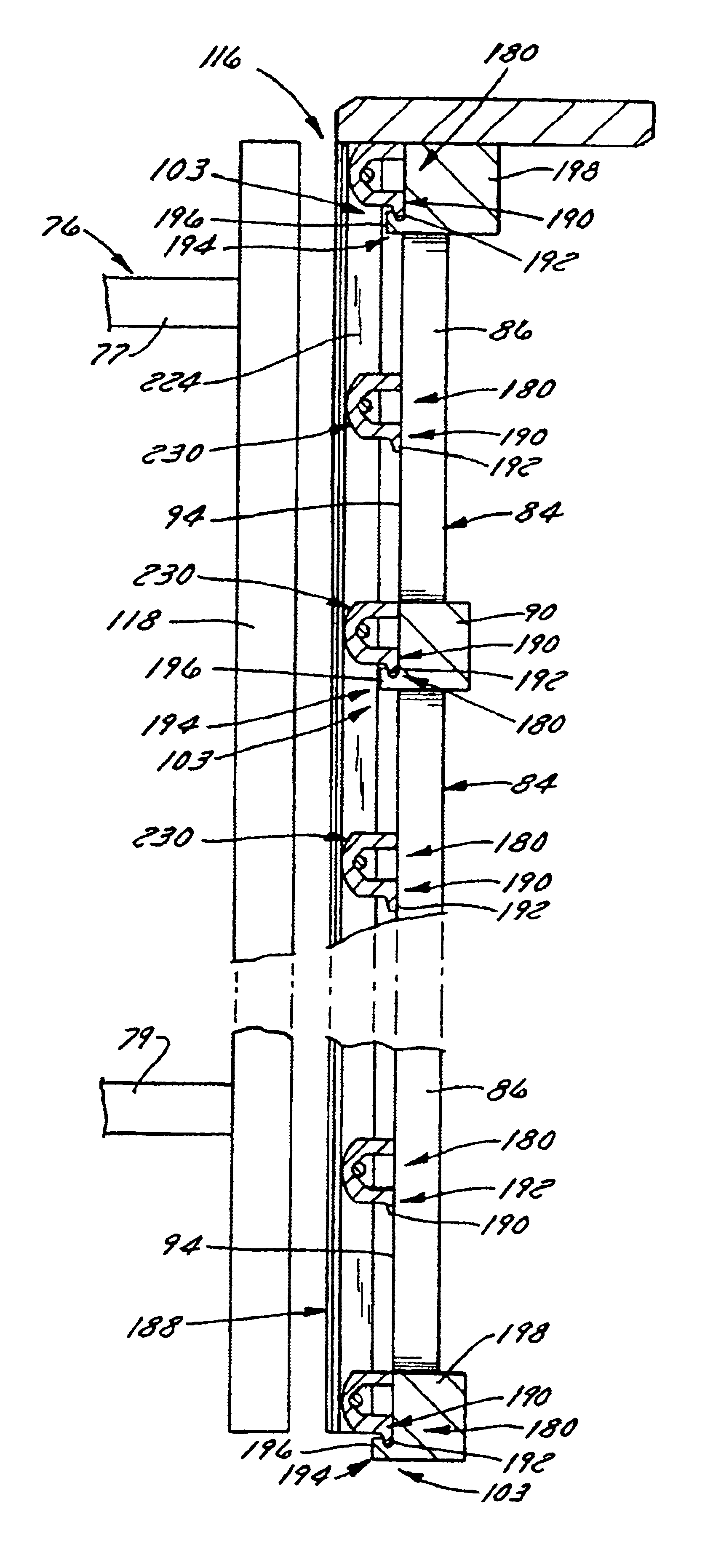
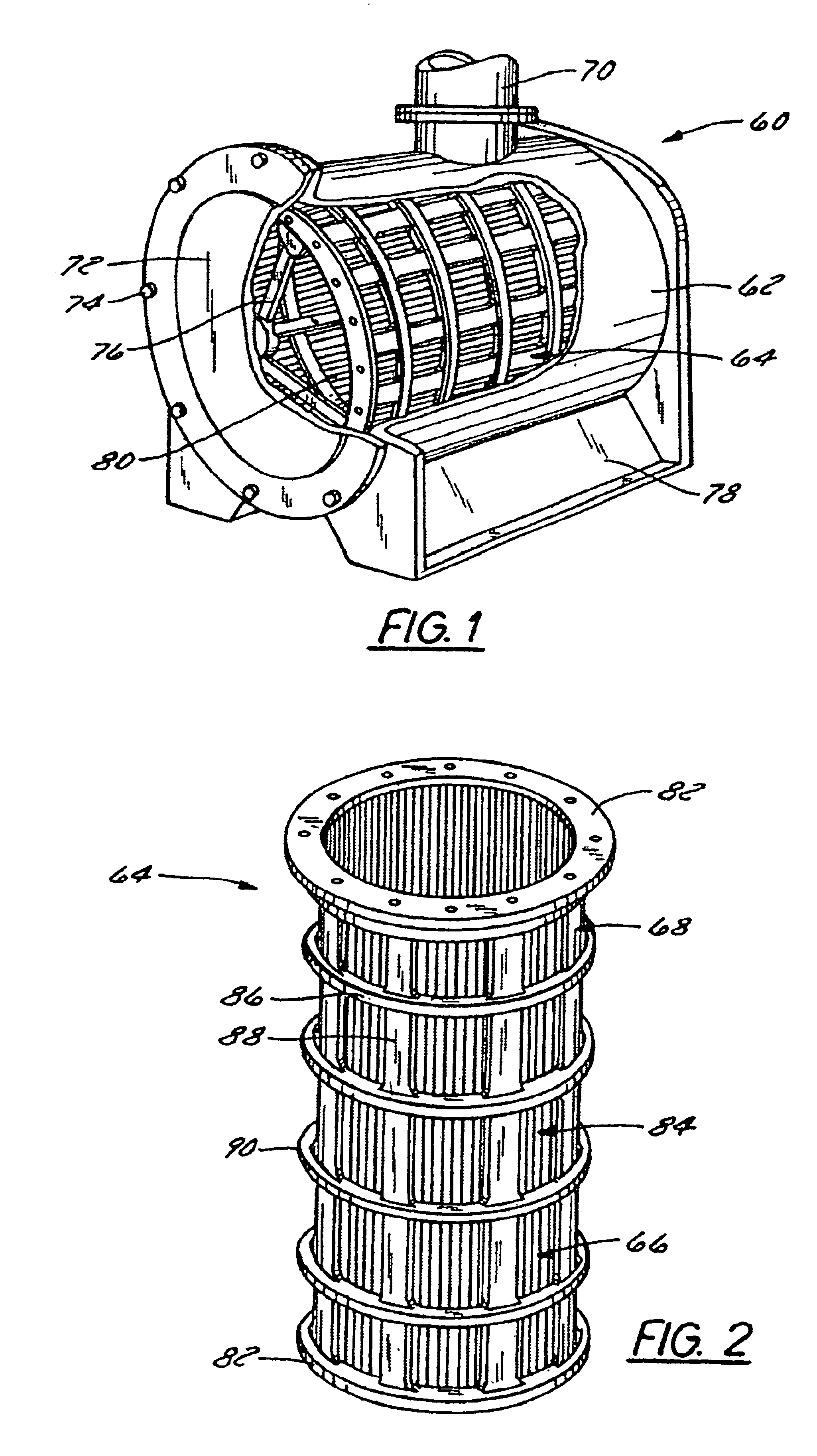
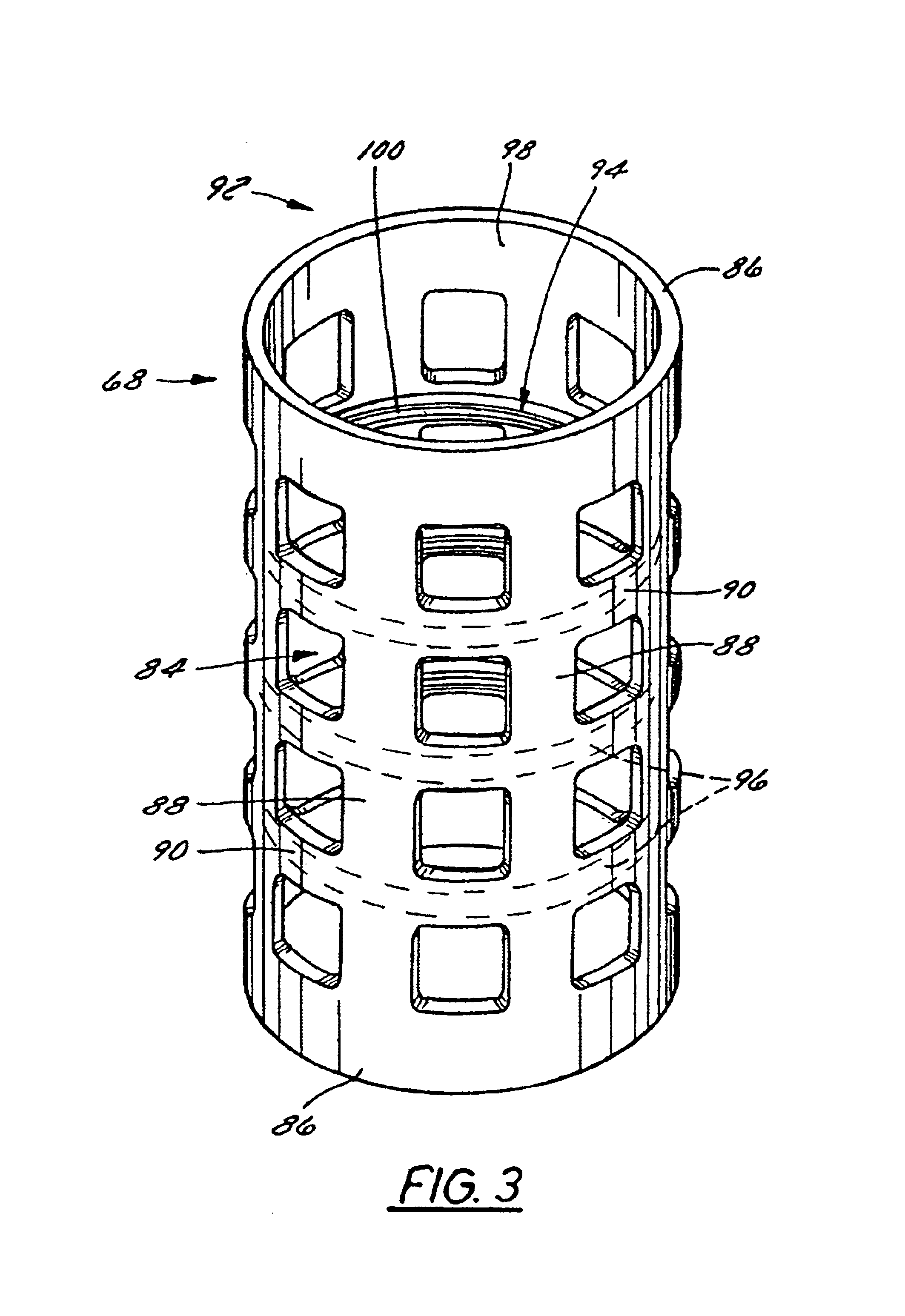
[0085]FIG. 1 illustrates a screening apparatus 60 that has a housing 62 and a screen cylinder assembly 64 disposed in the housing 62. As is shown in more detail in FIG. 2, the screen cylinder 64 is comprised of a perforate screen media 66 disposed in a perforate frame 68. The apparatus 60 has an inlet (not shown), through which slurry passes, and an outlet 70, from which filtrate exits. Typically, the apparatus 60 also has a contaminant discharge (not shown), through which filtered or rejected material is removed. So that maintenance can be performed, including removal of the screen cylinder 64, the apparatus 60 typically includes a cover 72 attached to the housing 62, such as by fasteners 74. A rotor 76 can be and preferably is disposed inside the screening apparatus 60. Typically, the rotor 76 is disposed inside the screen media 66, but other arrangements are possible. The housing 62 of the screening apparatus 60 shown in FIG. 1 rests upon a pedestal 78 that spaces the apparatus 6...


PUM

PropertyMeasurementUnit
weight ratioaaaaaaaaaa
angleaaaaaaaaaa

Abstract

A pulp screen cylinder that includes screen media releasably engaged with a frame at spaced locations opposing movement of the media away from the frame during screening. A preferred frame includes a plurality of spaced engaging structures that releasably engage screen media. A preferred frame includes an arrangement of flow windows that are triangular or rhomboid. A preferred method includes producing a frame cylinder by centrifugal casting and machining flow windows using a jet cutting process. A preferred screen media has a plurality of spaced apart engaging structures that each releasably engages the frame at spaced apart locations. A preferred screen media is of wedgewire construction having engaging structure carried by a plurality of spaced wire retaining clips. A preferred clip has vee-shaped rounded slots and an arm thicker than an end wall. A preferred engaging structure includes a projection that has a lip or hook for releasable interlocking engagement.

Description

CROSS REFERENCE TO RELATED APPLICATION[0001]This application claims priority under 35 U.S.C. §119(e) to U.S. Provisional Patent Application No. 60 / 283,963, filed Apr. 16, 2001, the entirety of which is incorporated by reference herein.FIELD OF THE INVENTION[0002]The present invention relates generally to generally screens for use in pulp screening or filtering and more particularly to a pulp screen cylinder that includes perforate screen media supported by a perforate frame and a method of making and assembling the same.BACKGROUND OF THE INVENTION[0003]Screen cylinders have long been used in pulp and papermaking applications to screen fiber in a stock slurry. Screen cylinders typically consist of a perforate cylinder received in the housing of a screening apparatus. Stock flows through slots or holes in the sidewall of the screen cylinder where it eventually ends up being processed into pulp, paper or another fiber product. Fiber in the stock selectively passes through the slots or ...

Claims


Application Information

Patent Timeline
Patent Type & Authority Patents(United States)
IPC IPC(8): B01D33/067B01D33/06D21D5/00D21D5/16
CPCB01D33/067D21D5/16B01D33/11B01D2201/0415B01D2201/4084
Inventor LUTZ, MARK S.CROMELL, TIM J.
Owner KADANT BLACK CLAWSON LLC
Why Eureka
Try Eureka