Bondable, oriented, nonwoven fibrous webs and methods for making them

a technology of nonwoven fibrous webs and fibers, applied in the field of bonded nonwoven webs, can solve the problems of increasing the cost of the web, requiring undesirable compromises in processing steps or product features, and fibers with limited capacity to participate in fiber bonding, and achieves the effect of convenient bondability

Inactive Publication Date: 2005-07-12
3M INNOVATIVE PROPERTIES CO
View PDF29 Cites 187 Cited by
  • Summary
  • Abstract
  • Description
  • Claims
  • Application Information

AI Technical Summary

Benefits of technology

[0008]The present invention provides new nonwoven fibrous webs that exhibit many desired physical properties of oriented-fiber webs such as spunbond webs, but have improved and more convenient bondability. Briefly summarized, a new web of the invention comprises fibers of uniform diameter that vary in morphology over their length so as to provide longitudinal segments that differ from one another in softening characteristics during a selected bonding operation. Some of these longitudinal segments soften under the conditions of the bonding operation, i.e., are active during the selected bonding operation and become bonded to other fibers of the web; and others of the segments are passive during the bonding operation. By “uniform diameter” it is meant that the fibers have essentially the same diameter (varying by 10 percent or less) over a significant length (i.e., 5 centimeters or more) within which there can be and typically is variation in morphology. Preferably, the active longitudinal segments soften sufficiently under useful bonding conditions, e.g., at a temperature low enough, that the web can be autogenously bonded.

Problems solved by technology

Bonding of oriented-fiber nonwoven fibrous webs often requires an undesirable compromise in processing steps or product features.
Such steps are required because the meltspun or spunbond fibers themselves generally are highly drawn to increase fiber strength, leaving the fibers with limited capacity to participate in fiber bonding.
But addition of bonding fibers or other bonding material increases the cost of the web, makes the manufacturing operation more complex, and introduces extraneous ingredients into the webs.
While the art has recognized the deficiencies involved in bonding of oriented-fiber webs, no satisfactory solution is known to exist.
Also, the whole fiber-forming process is operated at a rather low speed, thereby decreasing efficiency.
The high level of drawing of meltspun or spunbond fibers limits their capacity for autogenous bonding.

Method used


Image

  • Bondable, oriented, nonwoven fibrous webs and methods for making them
  • Bondable, oriented, nonwoven fibrous webs and methods for making them
  • Bondable, oriented, nonwoven fibrous webs and methods for making them

Examples


examples 1-4

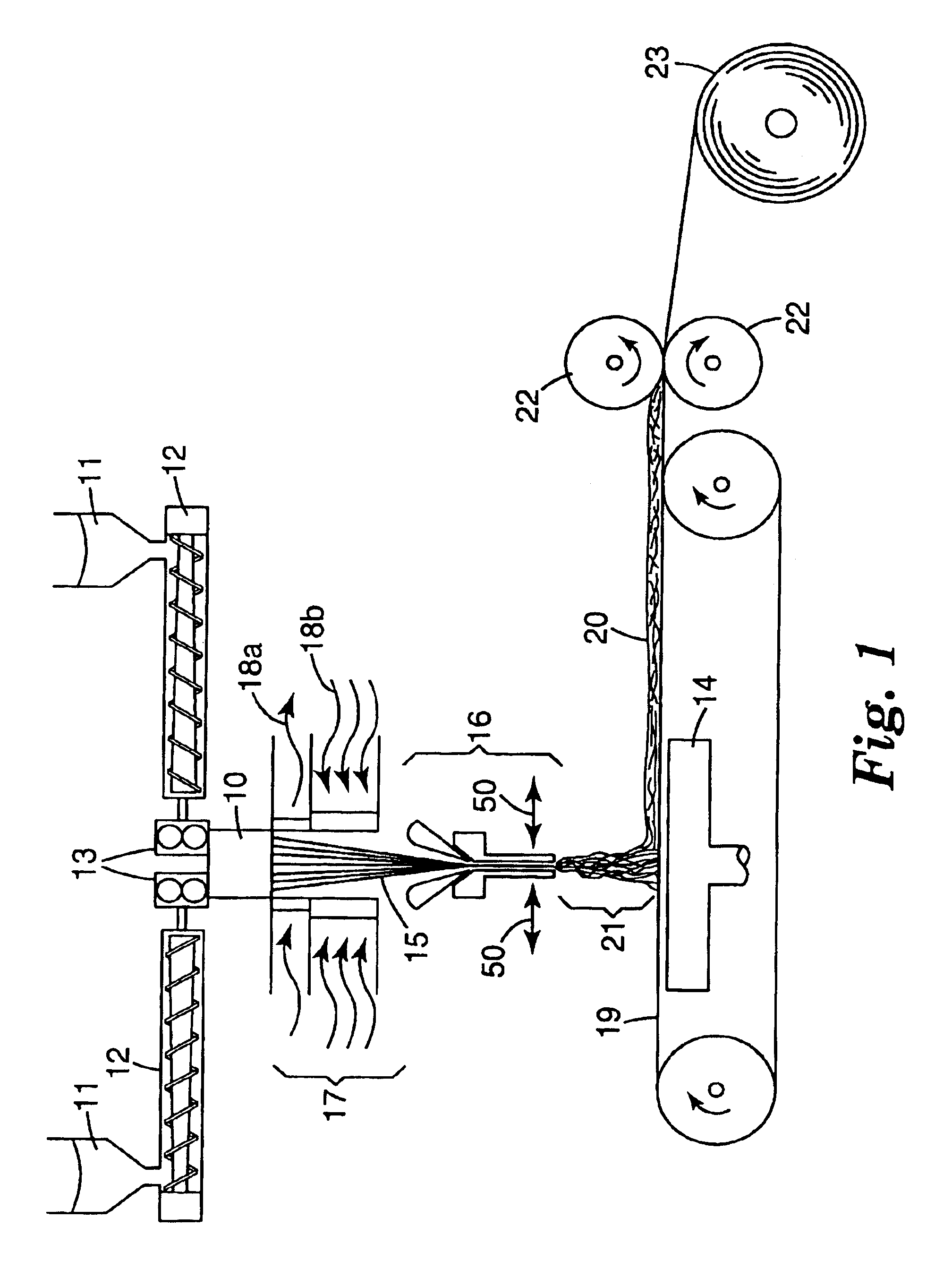
[0078]Apparatus as shown in FIGS. 1-3 was used to prepare four different fibrous webs from polyethylene terephthalate having an intrinsic viscosity of 0.60 (3M PET resin 651000). In each of the four examples PET was heated to 270° C. in the extruder (temperature measured in the extruder 12 near the exit to the pump 13), and the die was heated to a temperature as listed in Table 1 below. The extrusion head or die had four rows of orifices, and each row had 21 orifices, making a total of 84 orifices. The die had a transverse length of 4 inches (101.6 millimeters). The hole diameter was 0.035 inch (0.889 mm) and the L / D ratio was 6.25. The polymer flow rate was 1.6 g / hole / minute.

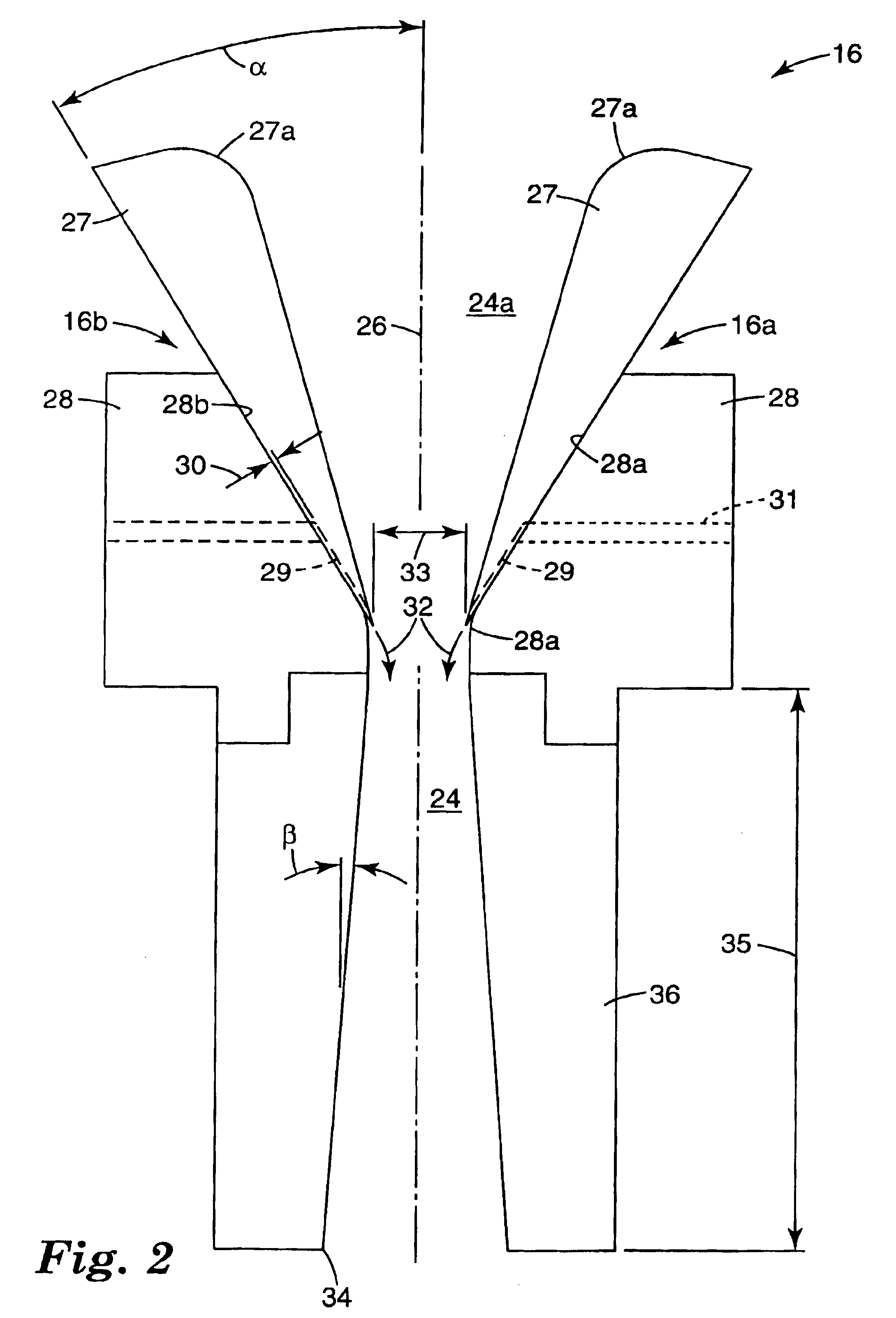
[0079]The distance between the die and attenuator (dimension 17 in FIG. 1) was 15 inches (about 38 centimeters), and the distance from the attenuator to the collector (dimension 21 in FIG. 1) was 25 inches (slightly less than 64 centimeters). The air knife gap (the dimension 30 in FIG. 2) was 0.030 inch (0.762 ...

examples 5-8

[0087]Fibrous webs were prepared on apparatus as shown in FIGS. 1-3 from polybutyl terephthalate (PBT-1 supplied by Ticona; density of 1.31 g / cc, melting point 227° C., and glass transition temperature 66° C.). The extruder temperature was set at 245° C. and the die temperature was 240° C. The polymer flow rate was 1 gram per hole per minute. The distance between the die and attenuator was 14 inches (about 36 centimeters), and the attenuator to collector distance was 16 (about 41 centimeters). Further conditions are stated in Table 4 and other parameters were generally as given for Examples 1-4.

[0088]

TABLE 4ExampleAttenuator GapAttenuator GapAttenuator AirNo.Top (mm)Bottom (mm)Flow (ACMM)56.834.342.8364.574.374.5974.573.914.0587.755.542.86

[0089]The webs were collected in an unbonded condition and then passed through an oven at 220° C. for one minute. FIG. 8 is an SEM at 500× showing bonds in a web of Example 5.

[0090]Birefringence was studied, with a range and average birefringence f...

examples 9-14

[0091]Webs of polytrimethylene terephthalate (PTT) fibers were prepared on apparatus as shown in FIGS. 1-3 using (in Examples 9-11) a clear version of the PTT (CP509201 supplied by Shell Chemicals) and (in Examples 12-14) a version that contained 0.4% TiO2 (CP509211). The extrusion die was as described in Examples 1-4 and was heated to a temperature as listed in Table 5 below. The polymer flow rate was 1.0 g / hole / minute.

[0092]

TABLE 5Die / ExtruderAttenuatorAttenuatorAttenuatorExampleTemperatureGap TopGap BottomAir FlowNo.(° C.)(mm)(mm)(ACMM)92603.863.201.73102653.863.202.49112653.683.024.81122653.282.823.82132653.282.824.50142604.503.781.95

[0093]The distance between the die and attenuator (dimension 17 in FIG. 2) was 15 inches (about 38 centimeters), and the distance from the attenuator to the collector (dimension 21 in FIG. 2) was 26 inches (about 66 centimeters). Other parameters were as given in Examples 1-4 or as described in Table 5. Webs were collected in an unbonded condition o...


PUM

PropertyMeasurementUnit
angleaaaaaaaaaa
diameteraaaaaaaaaa
angleaaaaaaaaaa

Abstract

Nonwoven fibrous webs comprise fibers of uniform diameter that vary in morphology along their length. The variation provides longitudinal segments that exhibit distinctive softening characteristics during a bonding operation. Some segments soften under the conditions of the bonding operation and bond to other fibers of the web, and other segments are passive during the bonding operation. Webs as described can be formed by a method that comprises a) extruding filaments of fiber-forming material; b) directing the filaments through a processing chamber in which the filaments are subjected to longitudinal stress; c) subjecting the filaments to turbulent flow conditions after they exit the processing chamber; and d) collecting the processed filaments; the temperature of the filaments being controlled so that at least some of the filaments solidify while in the turbulent field.

Description

FIELD OF THE INVENTION[0001]This invention relates to bonded nonwoven webs that comprise oriented fibers, and to methods for making such webs.BACKGROUND OF THE INVENTION[0002]Bonding of oriented-fiber nonwoven fibrous webs often requires an undesirable compromise in processing steps or product features. For example, when collected webs of oriented fibers such as meltspun or spunbond fibers are bonded (e.g., to consolidate the web, increase its strength, or otherwise modify web properties), a bonding fiber or other bonding material is typically included in the webs in addition to the meltspun or spunbond fibers. Alternatively or in addition, the web is subjected to heat and pressure in a point-bonding or area-wide calendering operation. Such steps are required because the meltspun or spunbond fibers themselves generally are highly drawn to increase fiber strength, leaving the fibers with limited capacity to participate in fiber bonding.[0003]But addition of bonding fibers or other bo...

Claims


Application Information

Patent Timeline
Patent Type & Authority Patents(United States)
IPC IPC(8): D01D5/08D01D5/098D04H1/558D04H3/02D04H3/16
CPCD01D5/0985D04H3/16D04H3/14Y10T428/24802Y10T442/637Y10T442/69Y10T442/652Y10T442/61Y10T442/625Y10T442/609Y10T442/608Y10T442/614D04H3/02D01D5/098
Inventor BERRIGAN, MICHAEL R.DE ROVERE, ANNE N.FAY, WILLIAM T.MUNRO, JILL R.PERCHA, PAMELA A.
Owner 3M INNOVATIVE PROPERTIES CO
Why Eureka
Try Eureka