Combined earth/star sensor system and method for determining the orbit and position of spacecraft

a technology of satellite orbit and position determination, which is applied in the direction of optical radiation measurement, navigation instruments, and instruments for comonautical navigation, can solve the problems of degrading the quality of measurements, affecting the accuracy of measurements, and the arrangement of several solar sensor heads is expensive, so as to simplify the integration and inherent radiation resistance, the effect of low mass and good stability

Inactive Publication Date: 2005-07-12
AIRBUS DEFENCE & SPACE
View PDF5 Cites 14 Cited by
  • Summary
  • Abstract
  • Description
  • Claims
  • Application Information

AI Technical Summary

Benefits of technology

[0015]By filtering out or acquiring a long-wave fraction of the radiation, e.g. by means of edge filters, the rim of the earth can be acquired particularly well and with particularly good stability. Additional degrees of freedom can be determined by model based tracking of the rim of the earth.
[0016]Further advantages of the invention include a low mass or possible redundancy because there is no need for further equipment such as for example gyros which were hitherto required for determining the orbit and the attitude. This results in simplified integration and inherent radiation resistance. Orbit determination is possible without the use of GPS, in particular also for near-earth and geostationary satallites. In this way, independent on-board operation can be achieved.

Problems solved by technology

This solution is associated with the disadvantage of the arrangement of several solar sensor heads used being very expensive, and of the lack of any yaw reference in the case of co-linearity of the earth and the sun.
Moreover, errors between the measuring axes of solar sensors and earth sensors, e.g. caused by inaccuracies during installation or as a result of thermal influence, can significantly degrade the quality of measurements.
Due to the their lack of radiation resistance, they are not suitable for use in orbits with substantial radiation load, e.g. for use in geosynchronous missions.
There is however a problem that the difference in brightness between the earth and stars has not been taken into account adequately.
Consequently, adequate acquisition of the earth and stars is not ensured.

Method used


Image

  • Combined earth/star sensor system and method for determining the orbit and position of spacecraft
  • Combined earth/star sensor system and method for determining the orbit and position of spacecraft
  • Combined earth/star sensor system and method for determining the orbit and position of spacecraft

Examples


Embodiment Construction

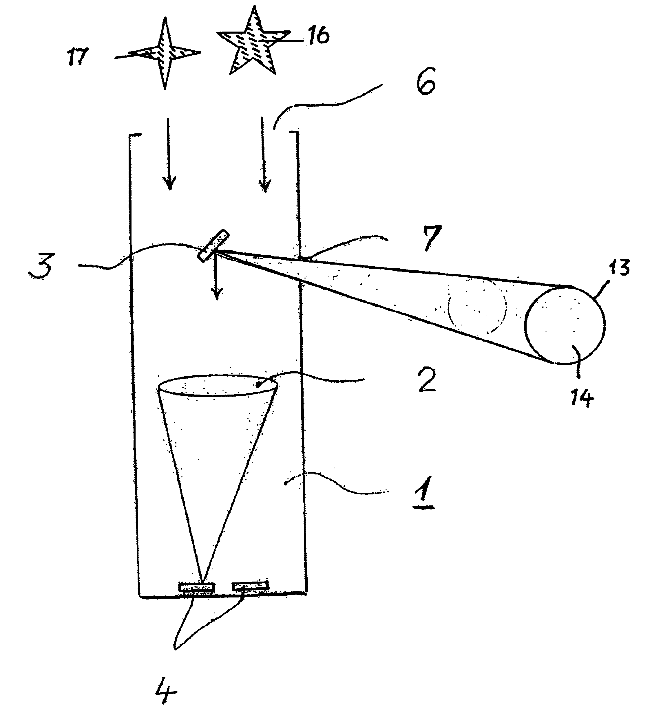
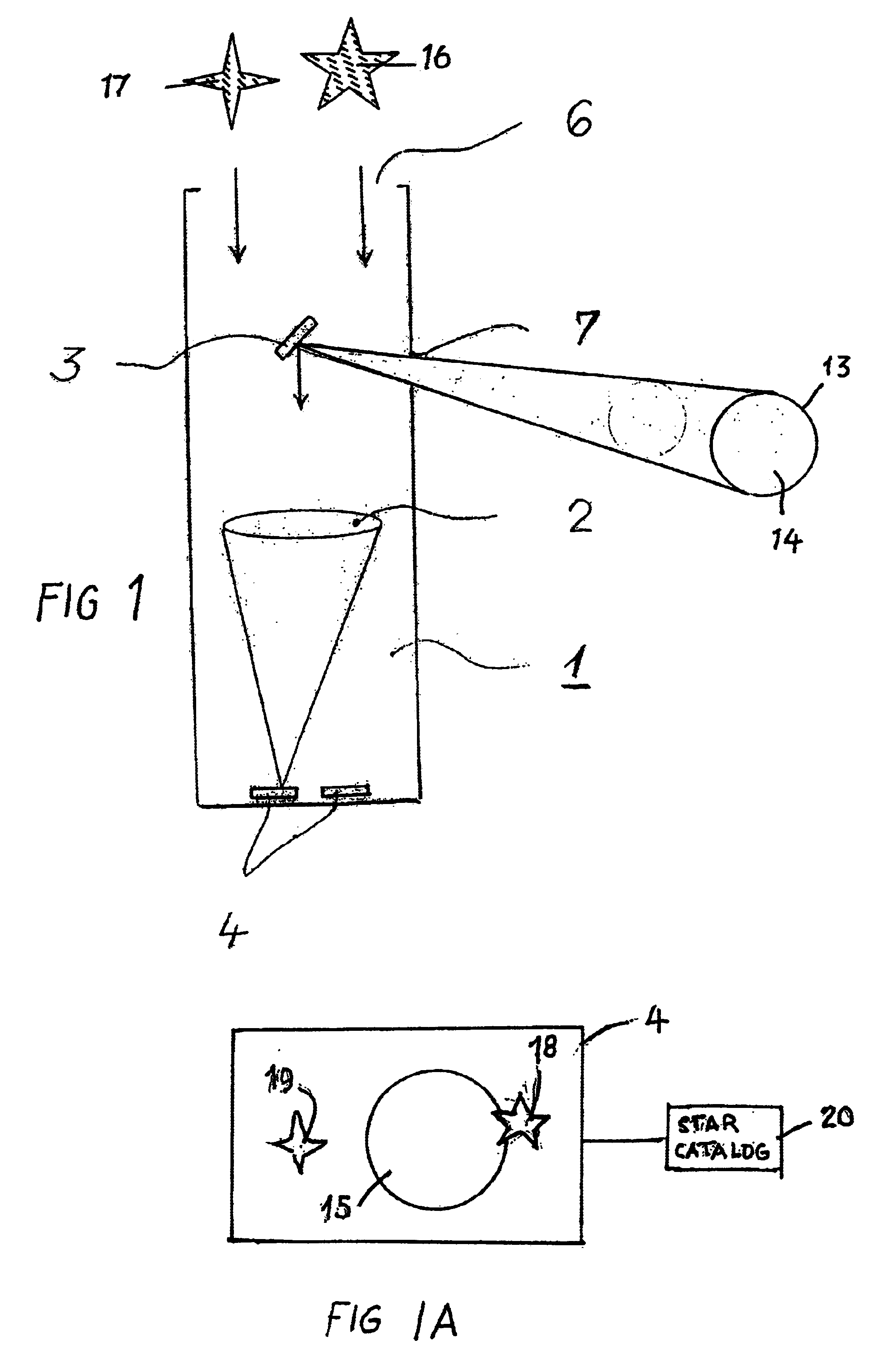
[0023]The combined earth-star sensor system 1 shown in FIG. 1 comprises a common optical arrangement 2, a deflection mirror 3, image pickup devices 4 and windows 6 and 7 for earth and star observation.

[0024]The system shown is in particular characterised in that the observation direction to the earth differs from the observation direction to the stars.

[0025]Starlight enters the window 6, passes the little deflection mirror 3, reaches the common optical arrangement 2 and is focussed onto the image pickup device 4. The light from the earth enters through the window 7, impinges on the deflection mirror 3 which directs it to the common optical arrangement 2. The common optical arrangement 2 focuses the light from the earth on the image pickup devices 4. In relation to a common optical arrangement 2, the image pickup devices 4 are arranged on a common focal plane according to a specified pattern. FIG. 3 provides an example of a possible arrangement of four image pickup devices which prov...


PUM


Abstract

A combined earth-star sensor system (1) for three-axis attitude determination of satellites in space comprises separate apertures with different directions of observation and common image pickup devices (4) for the earth sensor and the star sensor. A common optical arrangement (2) for earth observation and start observation, and a deflection mirror (3) for derivation of the laterally entering light from the earth, to the common optical arrangement (2) may be provided. In one focal plane there is a focal plane sensor with an array of image pickup devices (4) with the integration time being controllable. An evaluation unit determines the orbit and the attitude of the space vehicle from the attitude and movement of the stars and of the rim of the earth in the focal plane.

Description

BACKGROUND OF THE INVENTION[0001]The invention relates to a combined earth-star sensor system for three-axis attitude determination of satellites in space, as well as a method for determining the orbit and attitude of space vehicles.[0002]For earth-oriented satellites, infrared sensors are presently used to determine roll and pitch angles, while solar sensors are used to determine the yaw angle of the satellite. This solution is associated with the disadvantage of the arrangement of several solar sensor heads used being very expensive, and of the lack of any yaw reference in the case of co-linearity of the earth and the sun. Furthermore, evaluation additionally requires an exact knowledge of the attitude of the satellite on its orbit. Moreover, errors between the measuring axes of solar sensors and earth sensors, e.g. caused by inaccuracies during installation or as a result of thermal influence, can significantly degrade the quality of measurements.[0003]Known star sensors provide ...

Claims


Application Information

Patent Timeline
Patent Type & Authority Patents(United States)
IPC IPC(8): G05D1/08B64G1/36G01C21/02G01S3/786
CPCB64G1/361B64G1/365G01C21/025G01S3/7867G05D1/0883B64G1/244
Inventor DIEHL, HERMANNPLATZ, WILLIZINNER, HELMUTGOTTZEIN, EVELYNE
Owner AIRBUS DEFENCE & SPACE
Why Eureka
Try Eureka