Power supply unit, distributed power supply system and electric vehicle loaded therewith

a power supply system and power supply technology, applied in the direction of secondary cell servicing/maintenance, battery/fuel cell control arrangement, electrochemical generators, etc., can solve the problem that the remaining low-voltage cells cannot be fully charged before the end of the charge operation, and the voltage of all the series-connected cells cannot be shared uniformly across the circui

Inactive Publication Date: 2005-07-12
HITACHI LTD
View PDF8 Cites 37 Cited by
  • Summary
  • Abstract
  • Description
  • Claims
  • Application Information

AI Technical Summary

Benefits of technology

[0014]The present invention has been developed in view of the problems described above, and the object thereof is to provide an inexpensive, compact power supply unit which can correct the voltage variations among cells connected in series.
[0016]In the parallel-connected pair of the first cell group and the second cell group according to the invention, the first cell group and the second cell group are connected in parallel through a current limiter. The current limiter limits the current flowing between the first cell group and the second cell group, and prevents the overcurrent of the first cell group or the second cell group, thereby making it possible to protect the power supply unit at the time of a fault.
[0017]A plurality of series circuits including the parallel-connected pairs of the first cell group and the second cell group are connected in parallel. As a result, the capacitance, the output and the service life of the power supply unit can be variably increased.
[0020]According to still another aspect of the invention, there is provided a power supply unit, wherein the first cell group and the second cell group share at least one component element. As a result, the number of parts and the cost are reduced. The component element shared is preferably the electrolytic solution.
[0022]According to yet another aspect of the invention, there is provided a power supply unit, wherein the parallel-connected pairs of the first cell group and the second cell group are connected in parallel to a cell management circuit. As a result, the equalization of the voltage of the parallel-connected pairs can be enhanced and the conditions thereof can be detected.

Problems solved by technology

In the case where a plurality of cells are connected in series, the variations of capacitance, initial voltage and temperature from one cell. to another causes a different voltage for a different cell, thereby making it difficult for all the series-connected cells to share the voltage across the circuit uniformly.
Especially in the case where the lithium secondary cells or the electric double layer capacitors employing an organic solvent as an electrolytic solution are connected in series, voltage variations causes an overcharge or an overdischarge, often resulting in a rupture or a fire, or at least an overcharge or an overdischarge, which poses the problem of an extremely shortened service life of the cells.
As a result, the remaining low-voltage cells fail to be fully charged before the end of the charge operation.
As a result, the remaining high-voltage cells cannot be fully discharged before the end of the discharge operation.

Method used


Image

  • Power supply unit, distributed power supply system and electric vehicle loaded therewith
  • Power supply unit, distributed power supply system and electric vehicle loaded therewith
  • Power supply unit, distributed power supply system and electric vehicle loaded therewith

Examples


second embodiment

[0047]FIG. 3 is a diagram showing the invention. In FIG. 3, numeral 201 designates a current limiter. The first cells 101 and the second cells 102 are connected in parallel to each other through the current limiters 201. FIG. 3 represents a case in which electrical double layer capacitors 101cpa to 101cpn are used as the first cells 101.

[0048]The current limiters 201 are each a PTC (positive thermal conductor) having such a characteristic as to increase the resistance with a large current, a resistor or a fuse. The current limiters 201 limit the current flowing between the first cells 101 and the second cells 102 (the current flowing from the first cells to the second cells, and the current flowing in the reverse direction) and thereby prevent an overcurrent from flowing in the cells. Also, the parallel-connected cells are prevented from being shorted in chain in the case where the first cells 101 or the second cells 102 are shorted.

third embodiment

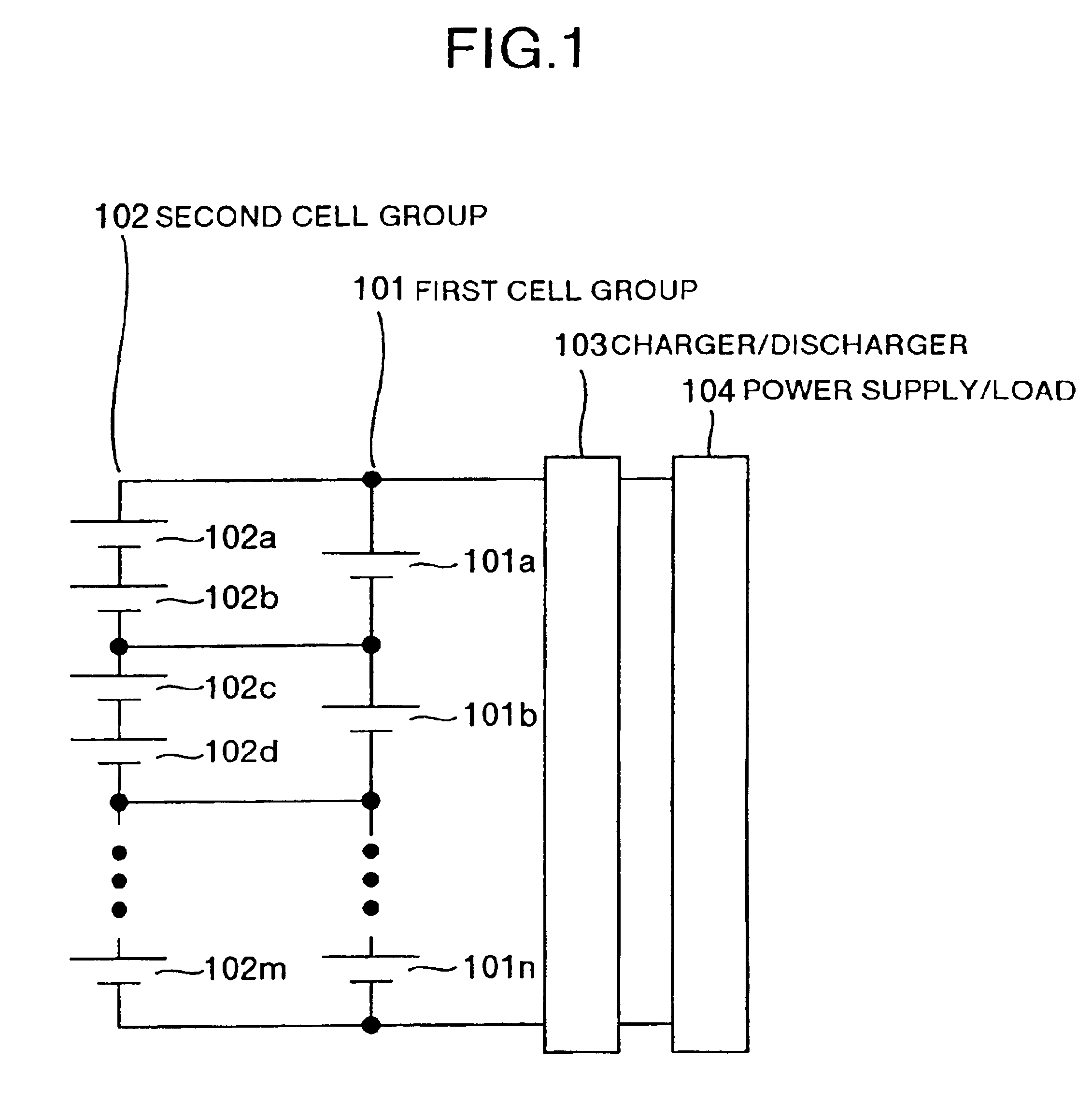
[0049]FIG. 4 is a diagram showing the invention. In FIG. 4, the parallel circuit of the first cells 101 and the second cells 102 shown in FIG. 1 and (a) in FIG. 2 is connected in parallel to another similar parallel circuit. The charger / discharger 103 and the power supply / load 104 are also connected. A plurality of series-connected circuits are connected in parallel in this way, so that the capacitance, the output and the service life of the power supply unit can be variably increased.

first embodiment

[0050]Also, as in the first embodiment, the charger / discharger 103 performs the charge operation, at an appropriate timing, up to a voltage at which the electrolytic solution of the second cells 102 is electrolyzed or at which the generated gas is recombined.

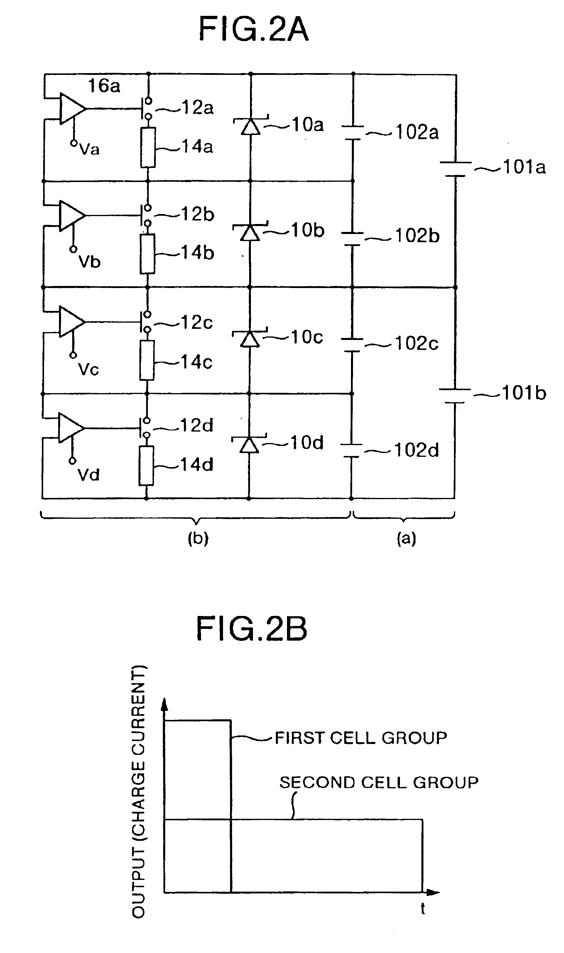
[0051]As a result, in a plurality of the parallel circuits of the first cells 101 and the second cells 102 in series, the second cells 102 are equalized at a voltage at which the electrolytic solution of the second cells 102 is electrolyzed or at which the generated gas is recombined. In FIG. 4, the portion (a) corresponds to FIG. 1 or the portion (a) in FIG. 2A, while the portion (b) corresponds to the configuration of FIG. 3. These portions are connected in parallel to configure the circuit of FIG. 4.


PUM

PropertyMeasurementUnit
voltageaaaaaaaaaa
voltageaaaaaaaaaa
operating voltageaaaaaaaaaa

Abstract

A power supply unit with improved charge / discharge operation for use in distributed power supply system or electric vehicles. The power supply unit includes a storage battery comprising a plurality of circuits connected in series. Each of the plurality of circuits includes a first cell group and a second cell group connected in parallel. The first cell group includes lithium secondary cells or electrical double layer capacitors. The second cell group utilizes an electrolyzable electrolytic solution, or is capable of generating recombinable gas. The second cell group may include lead cells, nickel hydrogen cells, nickel cadmium cells and / or fuel cells. A charger / discharger is provided for controlling charge / discharge of the storage battery adapted to charge the storage battery up to a voltage at which the electrolytic solution of the second cell group is electrolyzed, or to a voltage at which the generated gas is recombined.

Description

RELATED APPLICATIONS[0001]This application is a continuation of U.S. patent application Ser. No. 10 / 266,691, filed on Oct. 9, 2002, entitled “POWER SUPPLY UNIT, DISTRIBUTED POWER SUPPLY SYSTEM AND ELECTRIC VEHICLE LOADED THEREWITH,” which issued Mar. 2, 2004 as U.S. Pat. No. 6,700,349, and which is a continuation of U.S. patent application Ser. No. 10 / 083,645, filed on Feb. 27, 2002, entitled “POWER SUPPLY UNIT, DISTRIBUTED POWER SUPPLY SYSTEM AND ELECTRIC VEHICLE LOADED THEREWITH,” which issued Jan. 20, 2004 as U.S. Pat. No. 6,680,600. The disclosures of the above-identified applications are incorporated herein by reference in their entireties.BACKGROUND OF THE INVENTION[0002]The present invention relates to a power supply unit comprising a multiplicity of cells such as lithium secondary cells, nickel hydrogen cells, lead seal cells, electric double layer capacitors and fuel cells connected in series parallel, and a distributed power supply system and an electric vehicle including ...

Claims


Application Information

Patent Timeline
Patent Type & Authority Patents(United States)
IPC IPC(8): B60L11/18H02J7/00H02J7/02H01M10/06H01M10/44H01M10/52H01M12/06H01M16/00H02J7/34
CPCB60L11/185B60L11/1866B60L11/1868H01M10/441H01M10/52H01M16/00H02J7/0014H02J7/0021B60L11/1861Y02T90/121H01M10/05H01M10/06H01M12/06H01M2250/20Y02T10/7005Y02T10/7011Y02T10/7016Y02T10/7044Y02T10/7055Y02T10/7061Y02T10/7066Y02T90/128Y02T90/14Y02T90/32Y02T10/7072B60L53/11B60L58/22B60L58/20B60L58/15Y02E60/10Y02T10/70Y02T90/40Y02E60/50B82Y40/00Y02T90/12
Inventor EMORI, AKIHIKOKINOSHITA, TAKUYAMIYAZAKI, HIDEKI
Owner HITACHI LTD
Why Eureka
Try Eureka