Common mode choke coil with edgewise windings and line filter including same

Inactive Publication Date: 2005-07-12
MINEBEA CO LTD
View PDF7 Cites 8 Cited by
  • Summary
  • Abstract
  • Description
  • Claims
  • Application Information

AI Technical Summary

Benefits of technology

[0036]With the structure described above, the line filter of the present invention can remove high frequency noise by the common mode choke coil alone, not requiring by-path capacitors, whereby the line filter can be used in the high frequency band realizing downsizing and cost reduction. If by-path capacitors are employed for further enhancing perform

Problems solved by technology

The above three methods, however, have respective problems described below.
Therefore, the number of winding turns must be increased to increase impedance, which limits its usage to special application.
In any case, the frequency band between 150 kHz and 30 MHz, in which conductive noise is regulated, cannot be successfully covered.
However, the increase in the number of turns causes stray capacity of winding to increase.
As a result, the impedance starts declining at a lower frequency due to the effect of the stray capacity Cs, which prohibits an excellent core material from fully demonstrating its excellence.
And, the increased number of winding turns deteriorates heat radiation

Method used


Image

  • Common mode choke coil with edgewise windings and line filter including same
  • Common mode choke coil with edgewise windings and line filter including same
  • Common mode choke coil with edgewise windings and line filter including same

Examples


Example

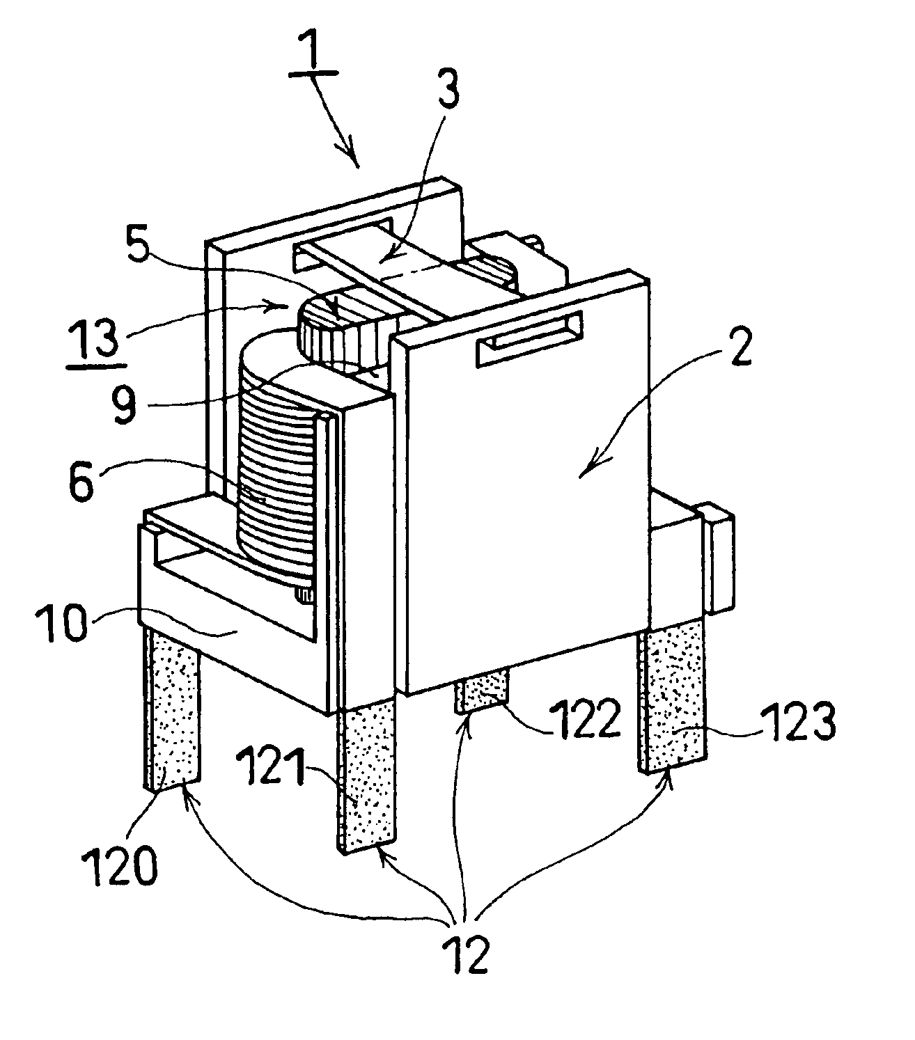
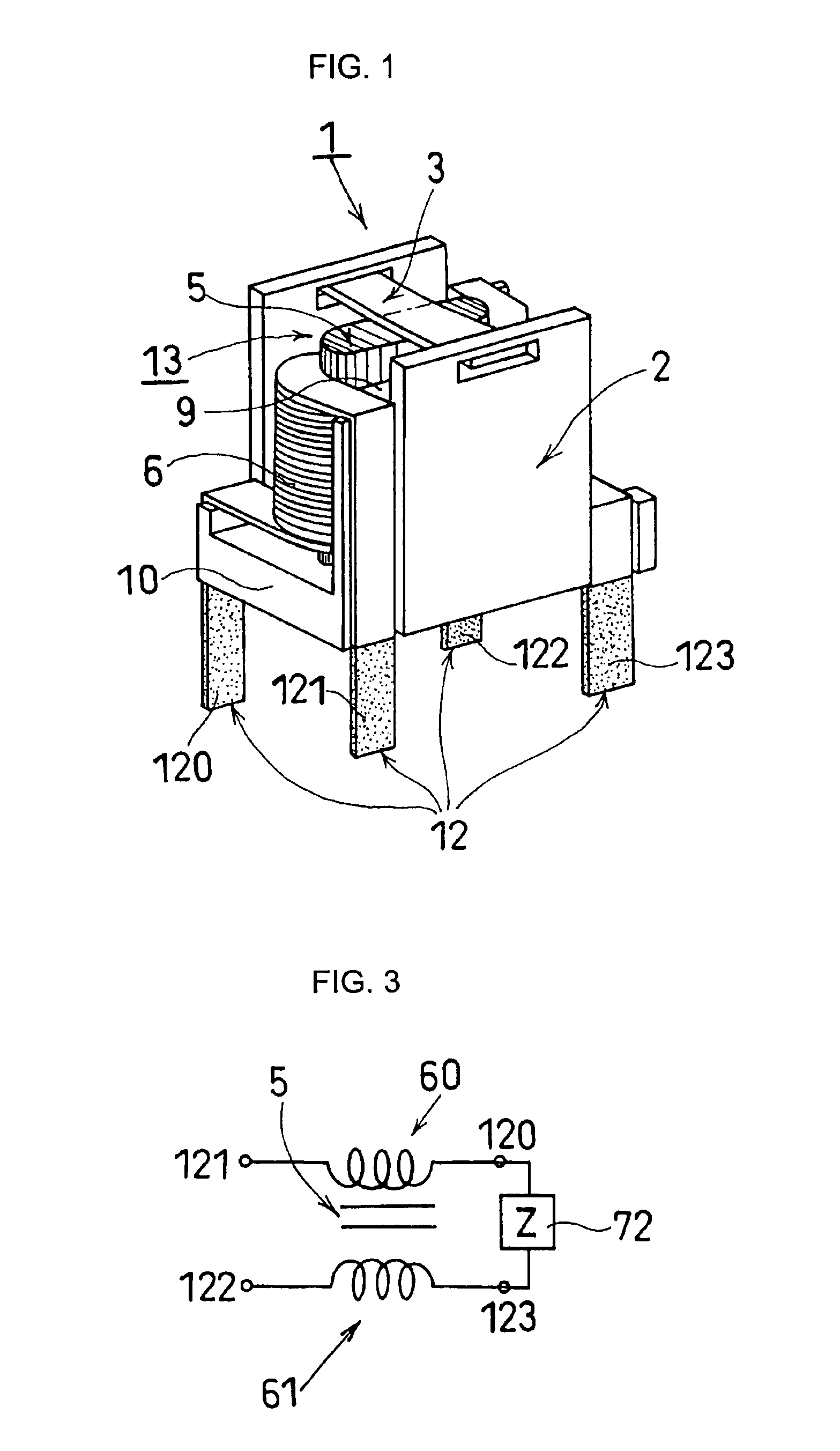
[0048]A preferred embodiment of the present invention will hereinafter be explained with reference to FIG. 1.

[0049]Referring to FIG. 1, a common mode choke coil 1 generally comprises a holder 2 made of a plastic resin, a coil section 13 mounted on a holder base section 10 of the holder 2, and a core securing plate spring 3. The coil section 13 comprises two edgewise windings 6 (only one is seen in the figure) of a rectangular insulated wire, a substantially square magnetic core 5 consisting of two core pieces each including two core legs (blinded in the figure), and a bobbin 9 having the core legs of the magnetic core 5 inserted therein and fixedly attached onto the holder 2 by means of the core securing plate spring 3. The bobbin 9 has its axis oriented perpendicular to a mounting board (not shown in the figure). End portions (terminations) 12 of the edgewise windings 6 which have their insulation resin peeled off and are plated with solder are attached to the board (not shown) aft...


PUM


Abstract

A common mode choke coil comprises: a Mn—Zn ferrite core which is shaped square, forms a closed magnetic path, and which has an initial permeability of at least 3,000 at 100 kHz and at least 100 at 10 MHz, respectively, at room temperature; and first and second edgewise windings which are formed respectively of first and second rectangular insulated wires. The first edgewise winding is provided around a core leg of the Mn—Zn ferrite core, and the second edgewise winding is provided around a core leg of the Mn—Zn ferrite core located oppositely to the core leg having the first edgewise winding provided therearound. This structure enables the core characteristics to be fully utilized without an influence of stray capacity of winding.

Description

BACKGROUND OF THE INVENTION[0001]1. Field of the Invention[0002]The present invention relates to a common mode choke coil and a line filter used in various electronic circuits, and more particularly to a common mode choke coil and a line filter having edgewise windings of a rectangular insulated wire.[0003]2. Description of the Related Art[0004]In recent years, since the miniaturization and enhanced performance of an electronic apparatus have been strongly demanded, a common mode choke coil used in a line filter is required to be downsized and improved in performance. Meanwhile, the characteristic of a common mode choke coil, for example, conductive noise level is controlled by regulation in a frequency band between 150 kHz and 30 MHz. Conventionally, a common mode choke coil uses a round insulated wire (refer to FIG. 1 of Japanese Patent Publication No. 2000-150243). Such a conventional common mode choke coil, as shown in FIG. 4, comprises: a bobbin 413 shaped cylindrical with a cy...

Claims


Application Information

Patent Timeline
IPC IPC(8): H01F1/12H01F27/255H01F1/34H01F17/04
CPCH01F1/344H01F27/255H01F2017/046
Inventor OKAMOTO, TOSHINORI
Owner MINEBEA CO LTD
Why Eureka
Try Eureka