Laser driver circuit

a laser diode and driver circuit technology, applied in the direction of laser details, semiconductor lasers, electrical apparatus, etc., can solve the problems of reducing the use of laser diodes such as non-bias driving, delay in optical emission timing, and negligible delay

Inactive Publication Date: 2005-07-12
RICOH KK
View PDF39 Cites 65 Cited by
  • Summary
  • Abstract
  • Description
  • Claims
  • Application Information

AI Technical Summary

Benefits of technology

[0059]According to the present invention, it becomes possible to achieve a control of the laser

Problems solved by technology

In the case of non-bias driving of laser diode, it takes some time after supplying of the driving current to the laser diode in response to the input signal, until there is formed carriers with a concentration level sufficient in the active layer of the laser diode for causing laser oscillation, and thus, there inevitably occurs a delay in the timing of optical emission.
Thus, the use of such a non-bias driving of laser diode has been limited to the applications in which such a delay is negligible.
Thus, in the case the laser diode is used for optical telecommunication, there occurs a deterioration of optical extinction ratio.
In the case the laser diode is used in laser printers, optical disk drives, digital copiers, and the like, on the other hand, there is caused the problem of the white background becoming dark because of the exposure to continuous optical emission of the laser diode.
Thus, the foregoing conventional approach can only provide an optical signal with an optical width smaller than the desired optical width for the optical signal.
Further, in the case of recording low concentration images on a recording medium by an optical output continuing for a short duration such as several nanoseconds or less, there arises a problem in that the optical output power does not reach the predetermined level'needed for the beam spot.
In such a case, the density of the recorded image becomes excessi

Method used


Image

  • Laser driver circuit
  • Laser driver circuit
  • Laser driver circuit

Examples


first embodiment

[First Embodiment]

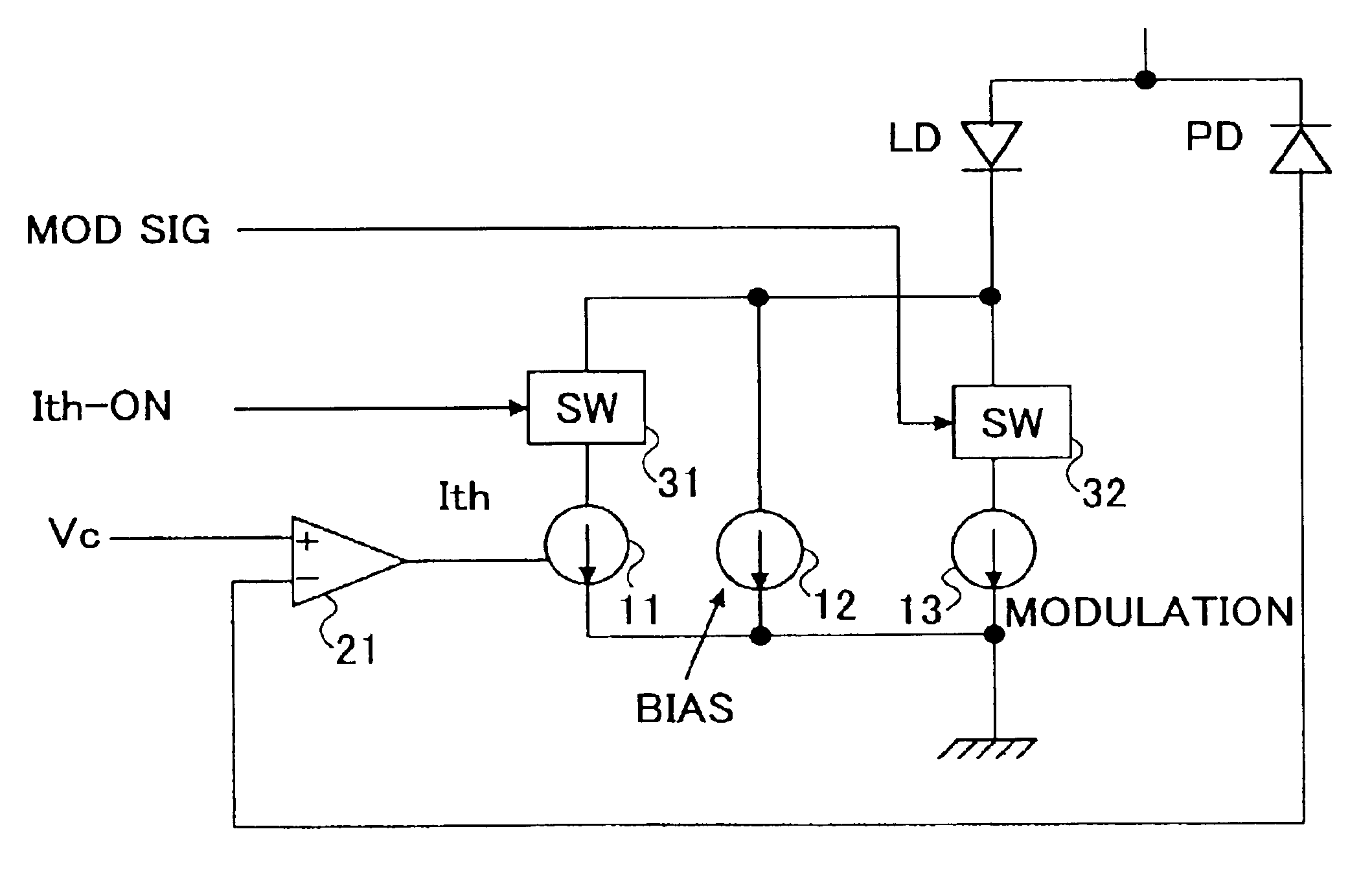
[0104]In a first embodiment, the present invention utilizes the characteristics of laser diode and achieves the driving of the laser diode by a sum of the bias current, threshold current and the drive current. Here, the drive current is set very small contrary to the conventional bias driving of laser diode.

[0105]In the non-biased state, it should be noted that the impedance of a laser diode takes a considerably large value, and it takes some time for the laser diode to become ready for laser oscillation in the case the threshold current is supplied to an unbiased laser diode because of the large inductance component, and the like, of the laser diode.

[0106]When a very small bias current, a magnitude of 1 mA would be sufficient, is supplied to the laser diode, on the other hand, the impedance of the laser diode is reduced significantly, and the laser diode becomes quickly ready for oscillation upon supplying of the threshold current in superposition to the bias curr...

second embodiment

[Second Embodiment]

[0182]FIG. 17 shows the principle of a laser driver circuit according to a second embodiment of the present invention, wherein those parts corresponding to the parts described previously are designated by the same reference numerals and the description thereof will be omitted.

[0183]Referring to FIG. 17, the laser driver circuit the laser driver circuit has a construction similar to the one described with reference to FIG. 3 except that there is provided an auxiliary modulation current source 14 parallel with other current sources 11-13, and thus, the laser diode LD is driven with a sum of the drive currents produced by the current sources 11-14. Thereby, it should be noted that the auxiliary modulation current source 14 is tuned on for only a very short interval such as 0.5-5 nm at the beginning of operation of the modulation current source 13. Similarly as before, the bias current source 12 supplies a drive current of about 1 mA, not exceeding several milliampere...

third embodiment

[Third Embodiment]

[0222]Hereinafter, a third embodiment of the present invention will be explained. The present embodiment deals with a temperature change of the laser diode and provides a laser driver circuit that maintains the output power of the laser diode constant when the operational temperature of the laser diode has been changed.

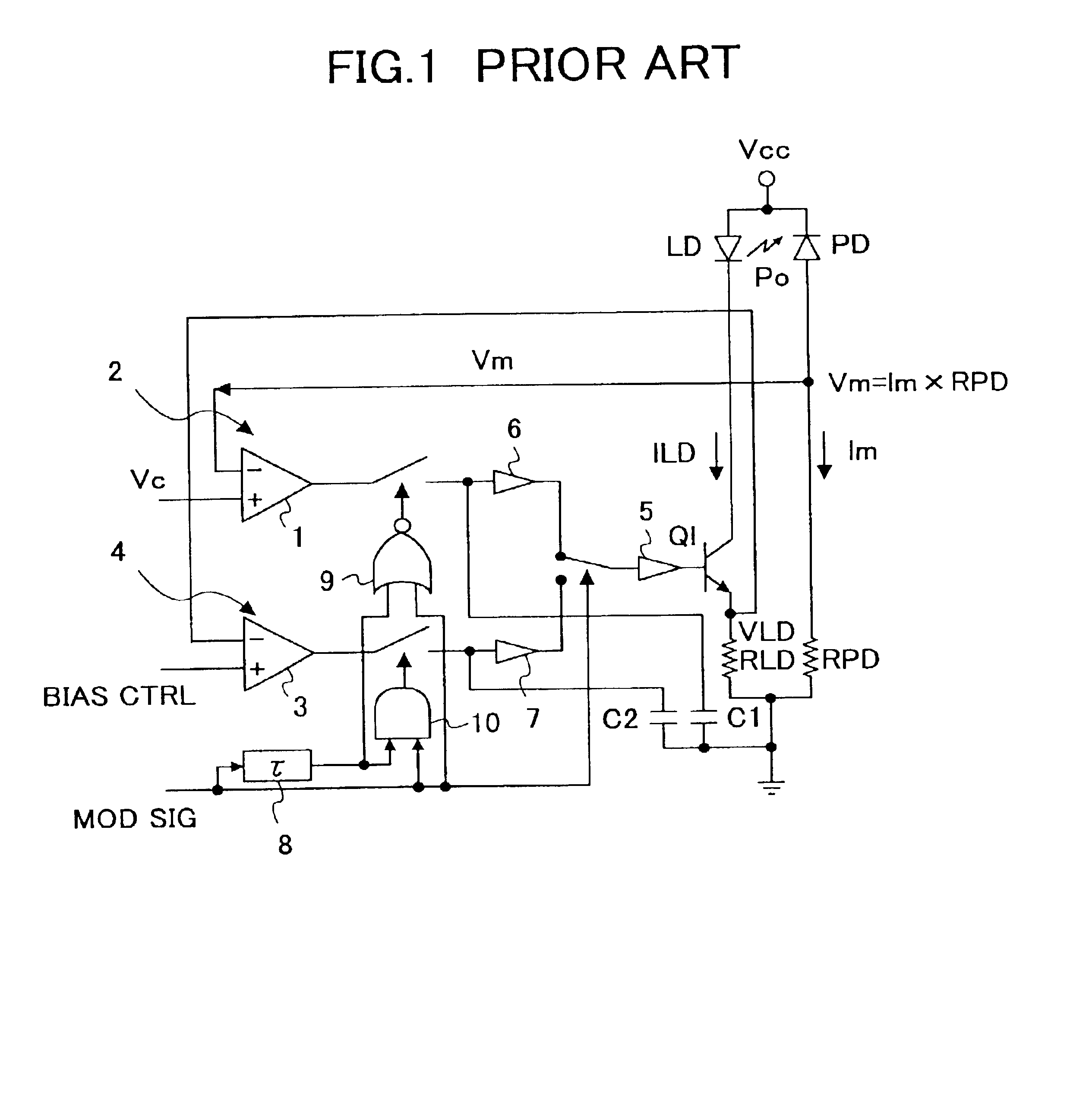
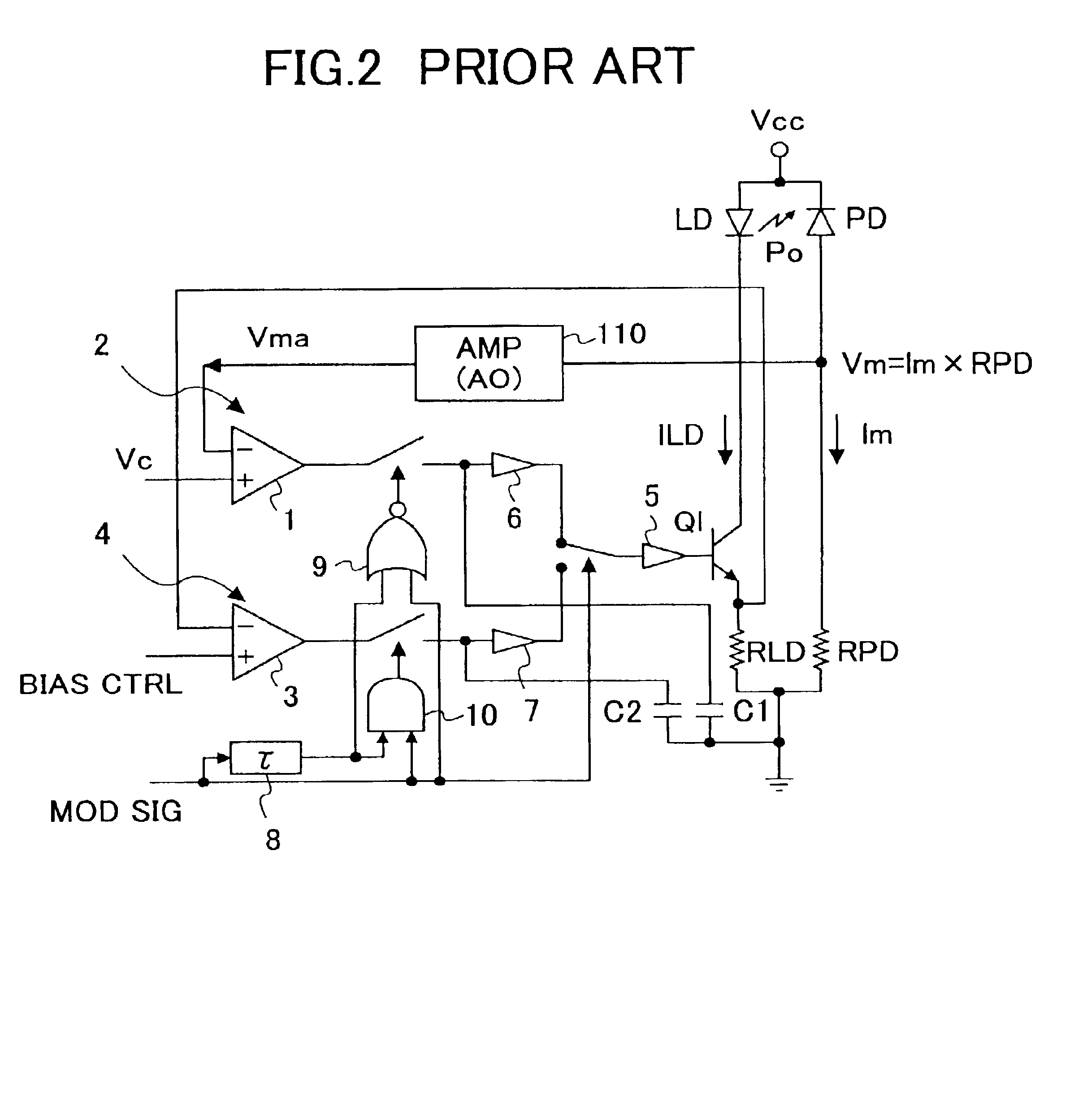
[0223]In the conventional art explained before with reference to FIG. 2, the optical-emission level control signal Vc controlling the optical emission level of the laser diode LD in the activated state thereof and a monitor voltage Vm produced by the photodetector PD are used to form a differential signal, and the differential signal thus formed is used to control the level of optical emission of the laser diode LD at the time of the activated state of the laser diode. Further, a bias level control signal controlling the optical emission level of the laser diode LD in the deactivated state thereof and the operational voltage VLD of the laser diode ob...


PUM


Abstract

A laser driver circuit includes a biasing current source, a threshold current source, and a modulation current source, wherein the threshold current source produces a threshold current in response to an input signal with an interval exceeding an interval of a modulation current such that said interval of the threshold current includes the interval of said modulation current. The laser driver circuit drives the laser diode by a sum of a continuous bias current, the threshold current and the modulation current.

Description

BACKGROUND OF THE INVENTION[0001]The present invention generally relates to driving of laser diode and formation of images, and more particularly to a laser diode driver circuit for use in laser printers, optical disk drives, digital copiers, and optical telecommunication systems for driving a laser diode, as well as an image formation apparatus that uses such a laser diode driver circuit.[0002]Conventionally, driving of a laser diode has been achieved either by a non-bias driving method or a biased driving method, wherein a non-bias driving method sets the bias current of the laser diode to zero and achieves the driving of the laser diode by a pulse current corresponding to an input signal. On the other hand, a biased driving method supplies a bias current to the laser diode with a level of the laser threshold current or less and drives the laser diode by superimposing a pulse current corresponding to an input signal to the bias current.[0003]In the case of non-bias driving of lase...

Claims


Application Information

Patent Timeline
IPC IPC(8): H01S5/042H01S5/00H01S5/0683
CPCH01S5/042H01S5/0427H01S5/0683
Inventor ISHIDA, MASAAKIEMA, HIDETOSHINIHEI, YASUHIROKYOUGOKU, HIROAKIOMORI, ATSUFUMI
Owner RICOH KK
Why Eureka
Try Eureka