
Thermal treatment system and method for controlling the system remotely to thermally treat sterile surgical liquid

a treatment system and thermal treatment technology, applied in the field of remote control of thermal treatment systems, can solve the problems of compromising sterile conditions, complicated procedures, and high flammability of glycol or other thermal transfer mediums

Inactive Publication Date: 2005-07-19
MICROTEK MEDICAL
View PDF71 Cites 56 Cited by
  • Summary
  • Abstract
  • Description
  • Claims
  • Application Information

AI Technical Summary

Benefits of technology

[0022]Alternatively, the thermal treatment system may be responsive to a remote control unit to enable users to control operation of the system remotely. The remote control unit may control various operating parameters and features of the system (e.g., desired temperatures, power, display, dislodgment mechanism, etc.), and preferably emits system commands in the form of code signals. A receiver is employed by the thermal treatment system to receive the transmitted signals and facilitate system operation in response to those signals.

Problems solved by technology

Additionally, the glycol or other thermal transfer medium is highly flammable or toxic and, in any event, complicates the procedure.
The Faries, Jr. et al U.S. Pat. No. 5,163,299 notes that scraping congealed liquid from the drape is undesirable in view of the potential for damage to the drape, resulting in a compromise of sterile conditions.
Although this hand manipulation is somewhat effective, it is not optimal, and often is inconvenient and constitutes an additional chore for operating room personnel.
Thus, the machine either provides sterile personnel with an additional task of controlling and monitoring the machine, or requires additional sterile personnel to perform the task, thereby increasing procedure costs and crowding the procedure site.
Further, the machine temperature indicator is generally poorly visible, and may similarly require personnel to be in close proximity to the machine to ascertain settings and liquid temperature.
The process of personnel frequently attending to the thermal treatment machine may become distracting to the procedure, especially when numerous machine inspections and / or control adjustments may be required.
Moreover, frequent inspections and / or adjustments may divert personnel from their medical procedure tasks at inopportune times, such as when complications arise, thereby increasing risk of injury to the patient.
This generally tends to decrease efficiency and may prevent crucial tasks from being completed at the proper time during the medical procedure, thereby risking injury to a patient.

Method used


Image

  • Thermal treatment system and method for controlling the system remotely to thermally treat sterile surgical liquid
  • Thermal treatment system and method for controlling the system remotely to thermally treat sterile surgical liquid
  • Thermal treatment system and method for controlling the system remotely to thermally treat sterile surgical liquid

Examples


Embodiment Construction

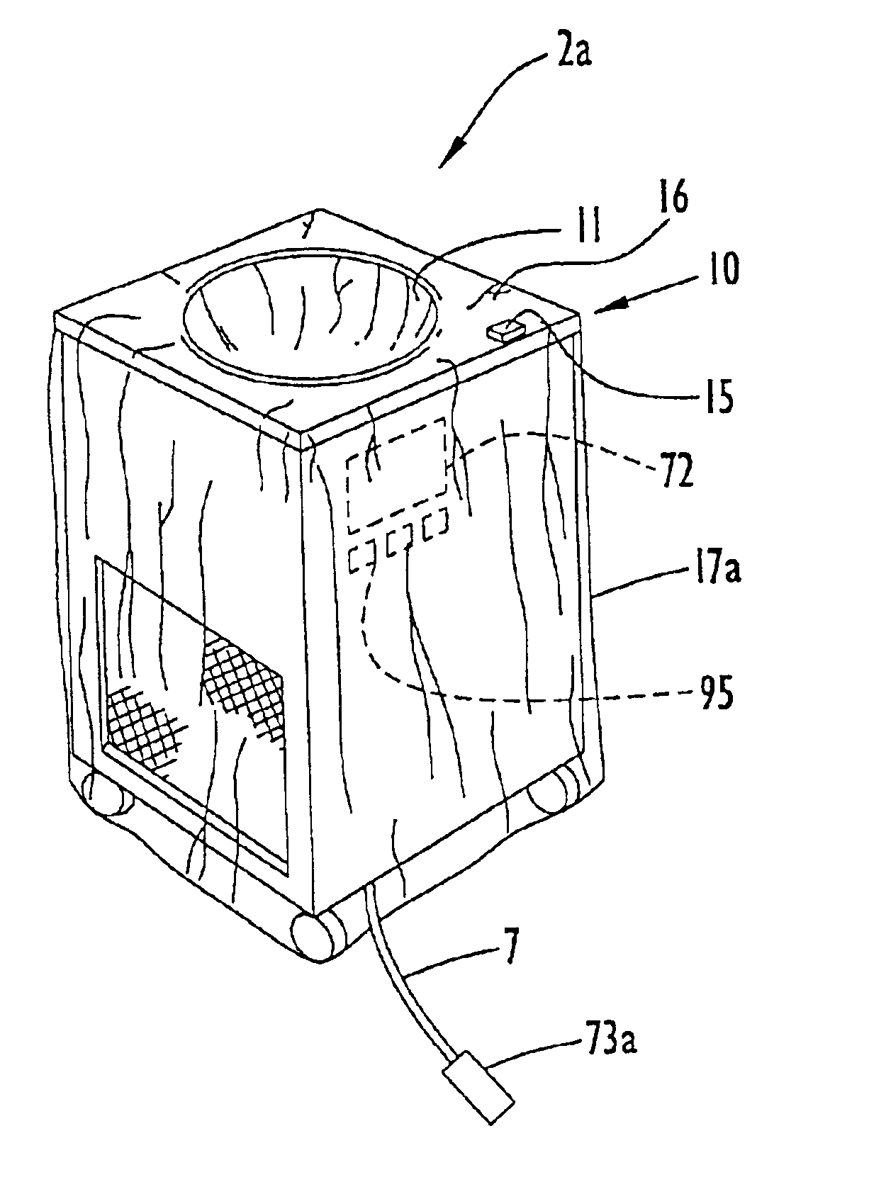
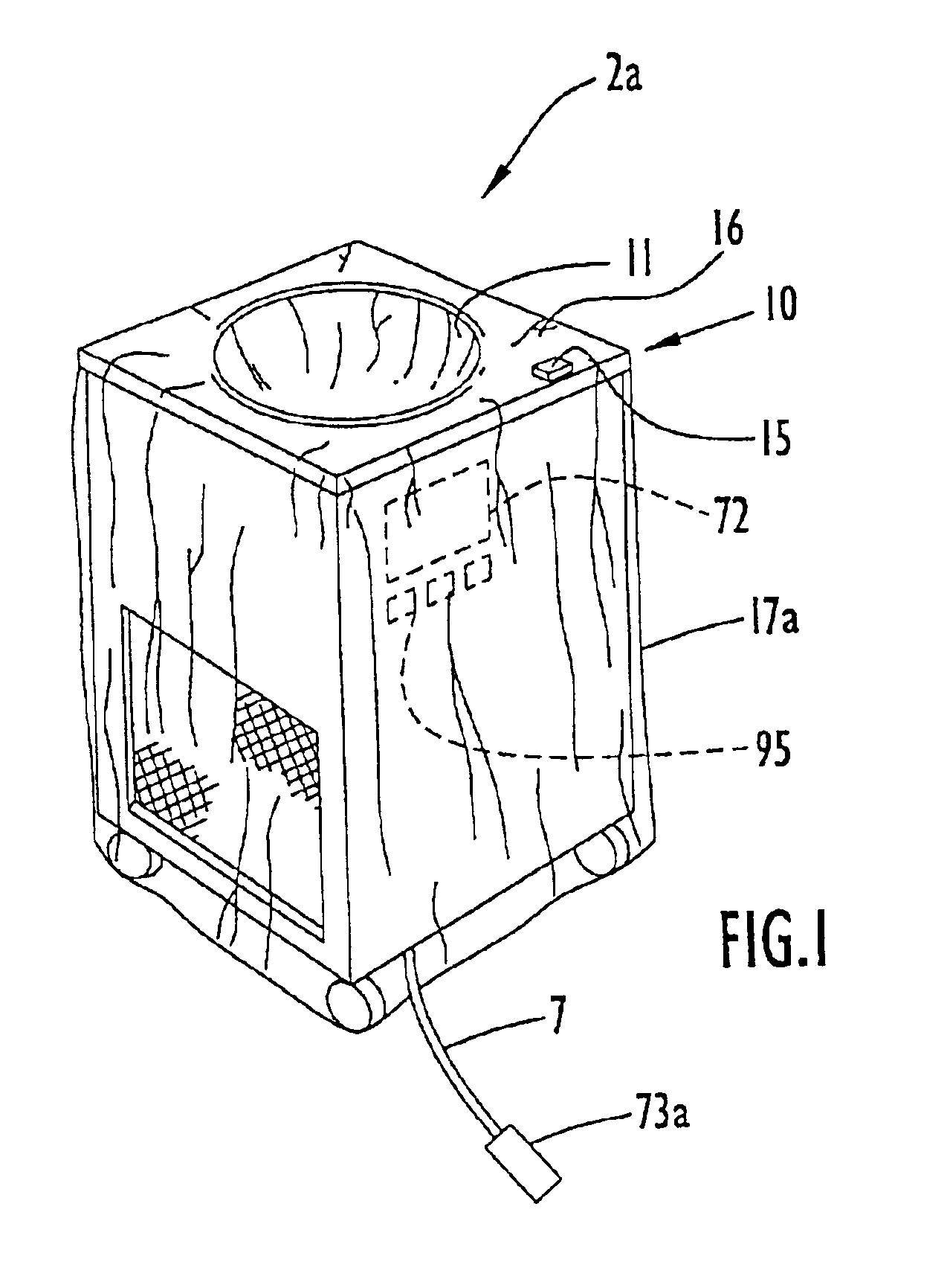
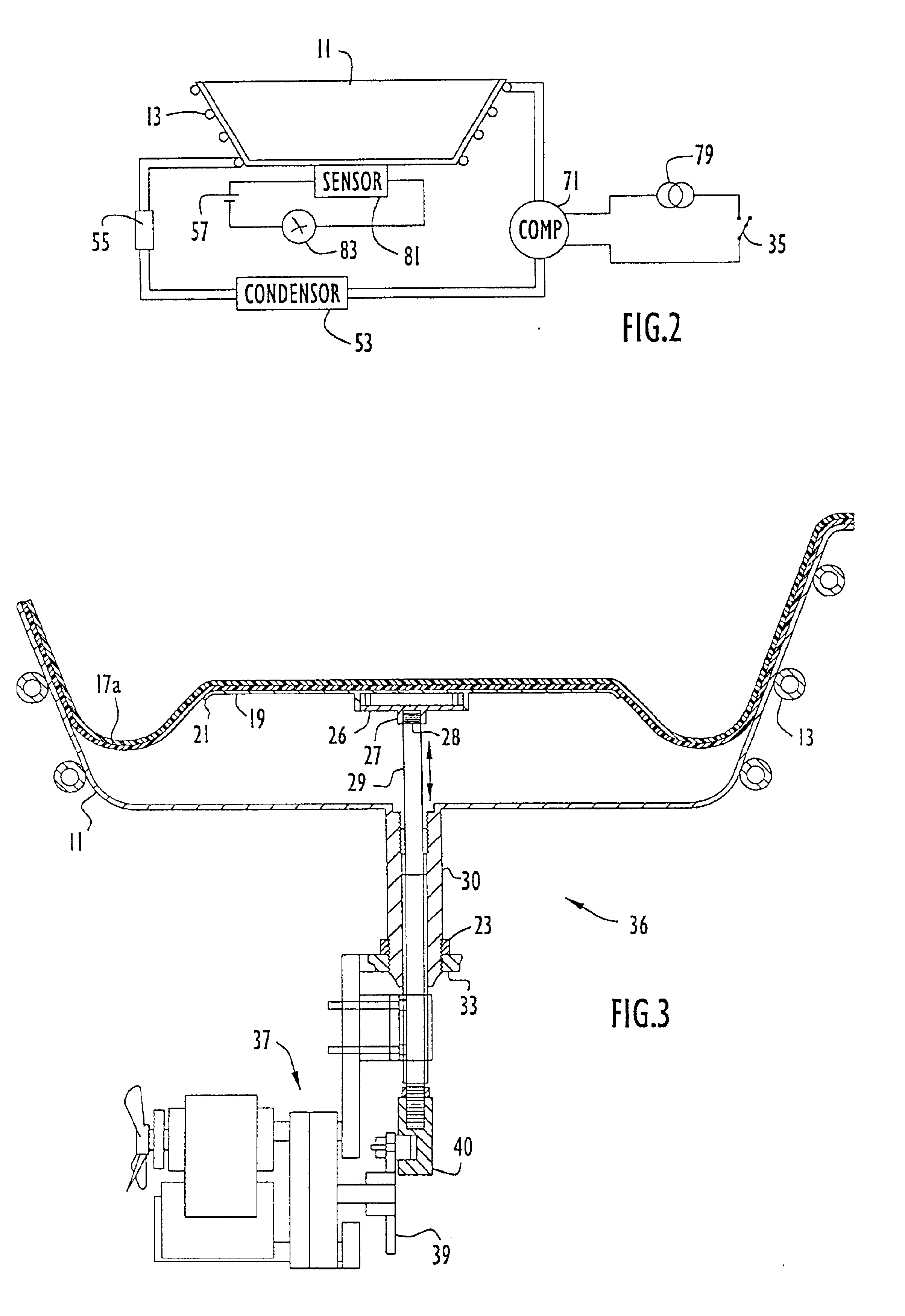
[0043]Referring to FIGS. 1-2 of the accompanying drawings, a thermal treatment system or machine 2a for cooling a sterile medium and generating surgical slush according to the present invention includes a cabinet or housing 10 with a top surface 16 having a basin 11 mounted thereon in an appropriately sized recess. Basin 11 may be of any shape, however, by way of example only, the basin is substantially circular. Basin 11 is made of thermally conductive material, typically stainless steel, and includes a generally flat bottom wall and frusto-conical side wall. A conventional refrigeration unit is disposed within cabinet 10 and typically includes a compressor 71, a condenser 53, a suitable thermal expansion valve 55 and an evaporator 13. The compressor is selectively actuable via an electrical power source 79 and an on / off power switch 35, and causes a suitable refrigerant fluid to flow through a series circuit including condenser 53, evaporator 13 and thermal expansion valve 55. The...


PUM

PropertyMeasurementUnit
temperatureaaaaaaaaaa
thicknessaaaaaaaaaa
temperaturesaaaaaaaaaa

Abstract

A thermal treatment system for thermally treating a sterile medium is controlled via a foot actuated switch to thermally treat the sterile medium to a desired temperature and / or form (e.g., slush). The thermal treatment system includes a basin recessed in a system top surface, while a surgical sterile drape is placed over the system and within the basin to form a drape container for containing the sterile medium. The basin may be configured to cool the sterile medium and form sterile surgical slush, or heat the sterile medium to provide warm sterile liquid. A dislodgment mechanism may be employed within a cooling basin to manipulate the drape and dislodge frozen pieces of sterile medium adhered to the drape. Information pertaining to the sterile medium and system operation may be displayed on a system display that has dimensions sufficient to provide visibility of the information to users located within extended ranges from the system. Alternatively, the thermal treatment system may be responsive to a remote control unit to enable users to control operation of the system remotely. The remote control unit may control various operating parameters and features of the system, and preferably emits system commands in the form of code signals. A receiver is employed by the thermal treatment system to receive the transmitted signals and facilitate system operation in response to those signals. In addition, the foot actuated switch and remote control unit may be utilized with thermal treatment systems having a plurality of heating and / or cooling basins.

Description

[0001]CROSS REFERENCE TO RELATED APPLICATIONS[0002]This application is a continuation of U.S. patent application Ser. No. 09 / 572,903, entitled “Remote Controlled Thermal Treatment System and Method for Controlling the System Remotely to Thermally Treat Sterile Surgical Liquid”, and filed May 17, 2000 now U.S. Pat. No. 6,371,121. The disclosure in the above-referenced patent application is incorporated herein by reference in its entirety.BACKGROUND OF THE INVENTION[0003]1. Technical Field[0004]The present invention pertains to improvements in methods and apparatus for heating and / or cooling sterile surgical media or liquids and collecting surgical sterile slush. In particular, the present invention pertains to remote control of thermal treatment systems to heat and / or cool sterile surgical media or liquids, and is an improvement of the methods and apparatus disclosed in U.S. Pat. No. 4,393,659 (Keyes et al), U.S. Pat. No. 4,934,152 (Templeton), U.S. Pat. No. 5,163,299 (Faries, Jr. et...

Claims


Application Information

Patent Timeline
Patent Type & Authority Patents(United States)
IPC IPC(8): A61B19/08A61B19/00A61B17/00H01H9/18H01H3/14H01H3/02A61B19/02A61F7/02A61L2/04H01H13/785
CPCA61F7/0241H01H13/785A61B19/081A61B2017/00973A61F2007/0094H01H3/14H01H9/181H01H2201/036A61B46/10
Inventor FARIES, JR., DURWARD I.HEYMANN, BRUCE R.
Owner MICROTEK MEDICAL
Learn More