Flow control product dispenser

a product dispenser and flow control technology, applied in the field of viscous product dispensing systems, can solve the problems of reducing the volume of the interior chamber, reducing the amount of product to be expelled through the opening, and reducing the retracting force slightly, so as to prevent unwanted product degradation, inhibit undesired product flow, and enlarge the space

Inactive Publication Date: 2005-07-19
SPATZ LAB
View PDF13 Cites 35 Cited by
  • Summary
  • Abstract
  • Description
  • Claims
  • Application Information

AI Technical Summary

Benefits of technology

[0016]When the desired amount of product has been dispensed and rotation of the screw is discontinued, the hoop will frictionally re-engage the interior surface of the container. Upon re-engagement, the twisted leg members will counter-rotate back to their original at-rest position. This causes the hub and screw to likewise counter-rotate in a direction opposite from the original direction of rotation by the predetermined angular amount. The counter-rotation translates into a reverse downward movement of the piston away from the container top openings. This movement neutralizes any pressure build-up in the chamber and thereby prevents unwanted product degradation and subsequent leakage out of the container top openings.
[0017]To further inhibit undesired product flow out of the container top openings, the openings may have a beveled cross-section. In this variation, each opening will increase in diameter from an outlet diameter to a larger inlet diameter. The larger inlet will provide an enlarged space for accumulating product from any increased pressure that may be present after operation of the screw and piston. Additionally, the inward taper helps to accelerate withdrawal of the product as the piston retracts.

Problems solved by technology

One of the inherent problems with the prior art devices is that moving the underlying structure toward the top of the container, decreases the volume of the interior chamber.
This pressurizes the product, which causes an additional small amount of product to be expelled through the openings, even after the user has already dispensed the desired amount of product and the user has stopped moving the underlying structure toward the top of the container.
Differential flexing between the first portion and the second portion during dispensing of the product results in a retracting force that slightly withdraws the elevator cup when dispensing is stopped.
A problem with the Fattori device is that the first portion, second portion and spring element are a continuous structure.
This produces an unpredictable diaphragm-like action resulting in erratic movement of the elevator cup.
The problem with the Franta et al. device is the upper surface valleys provide the same amount of retraction no matter what amount the fluid is pressurized.
Therefore, the device does not always compensate for variations in fluid pressure, and unwanted leakage can occur.

Method used


Image

  • Flow control product dispenser
  • Flow control product dispenser
  • Flow control product dispenser

Examples


Embodiment Construction

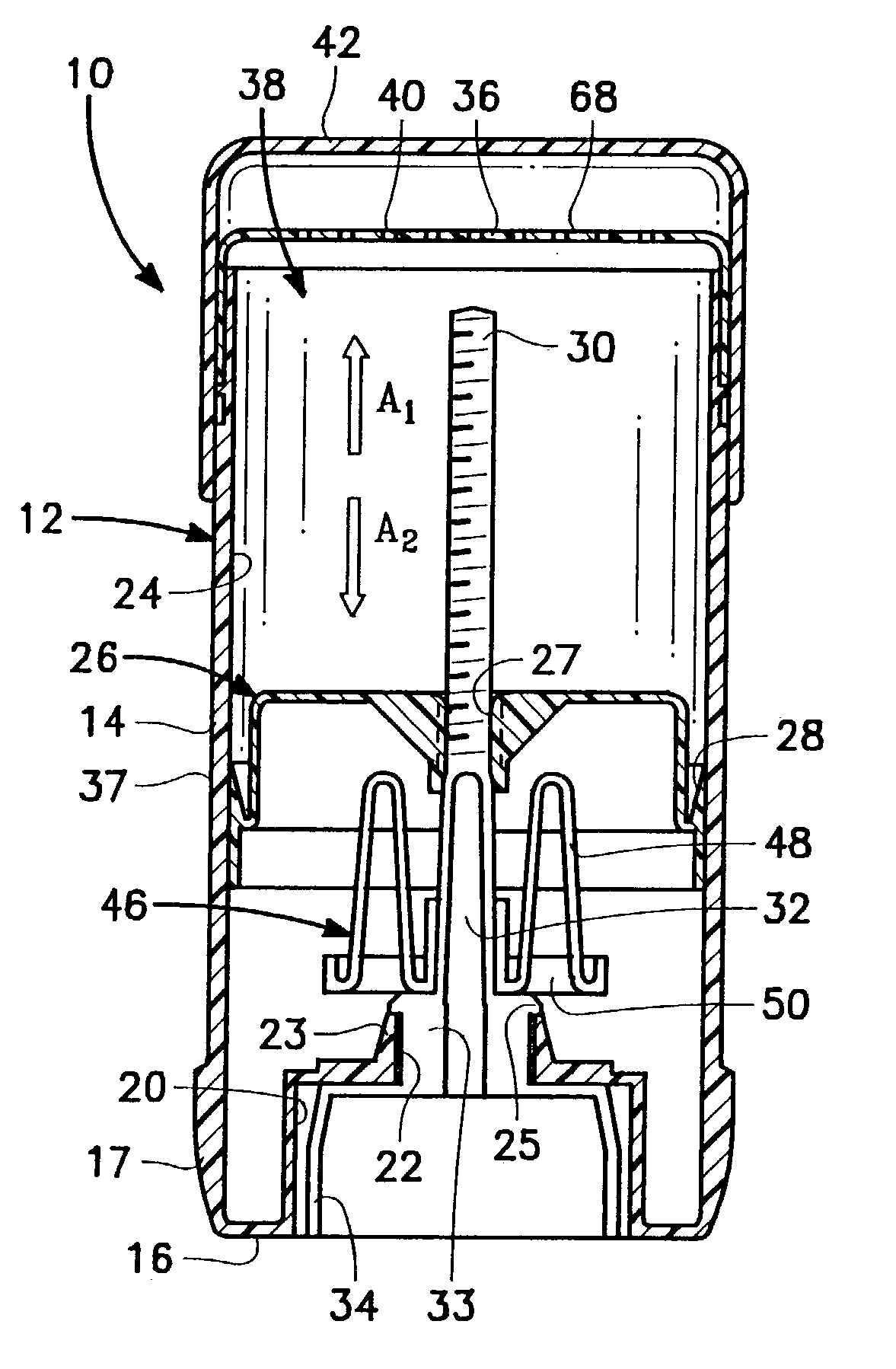
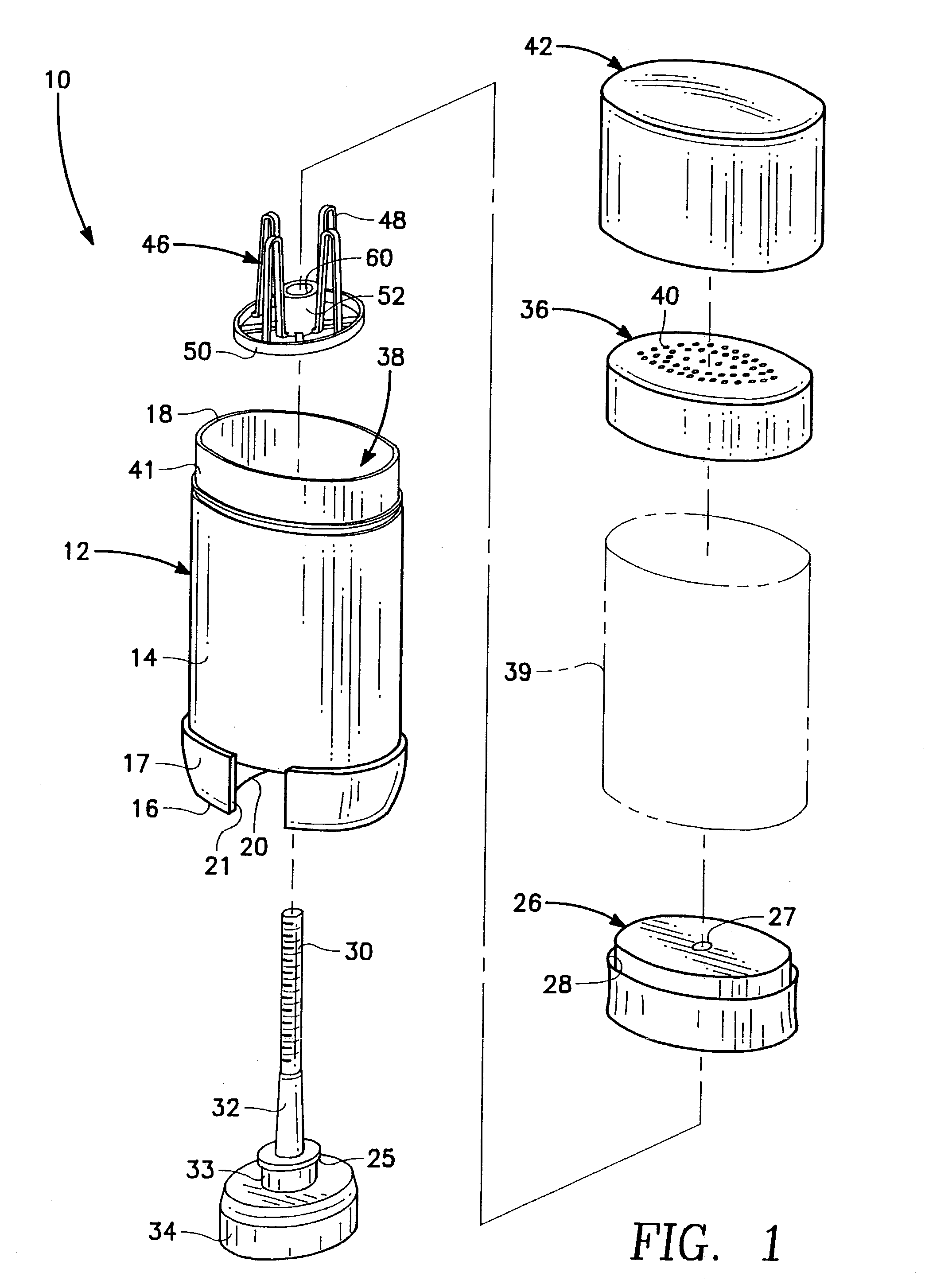
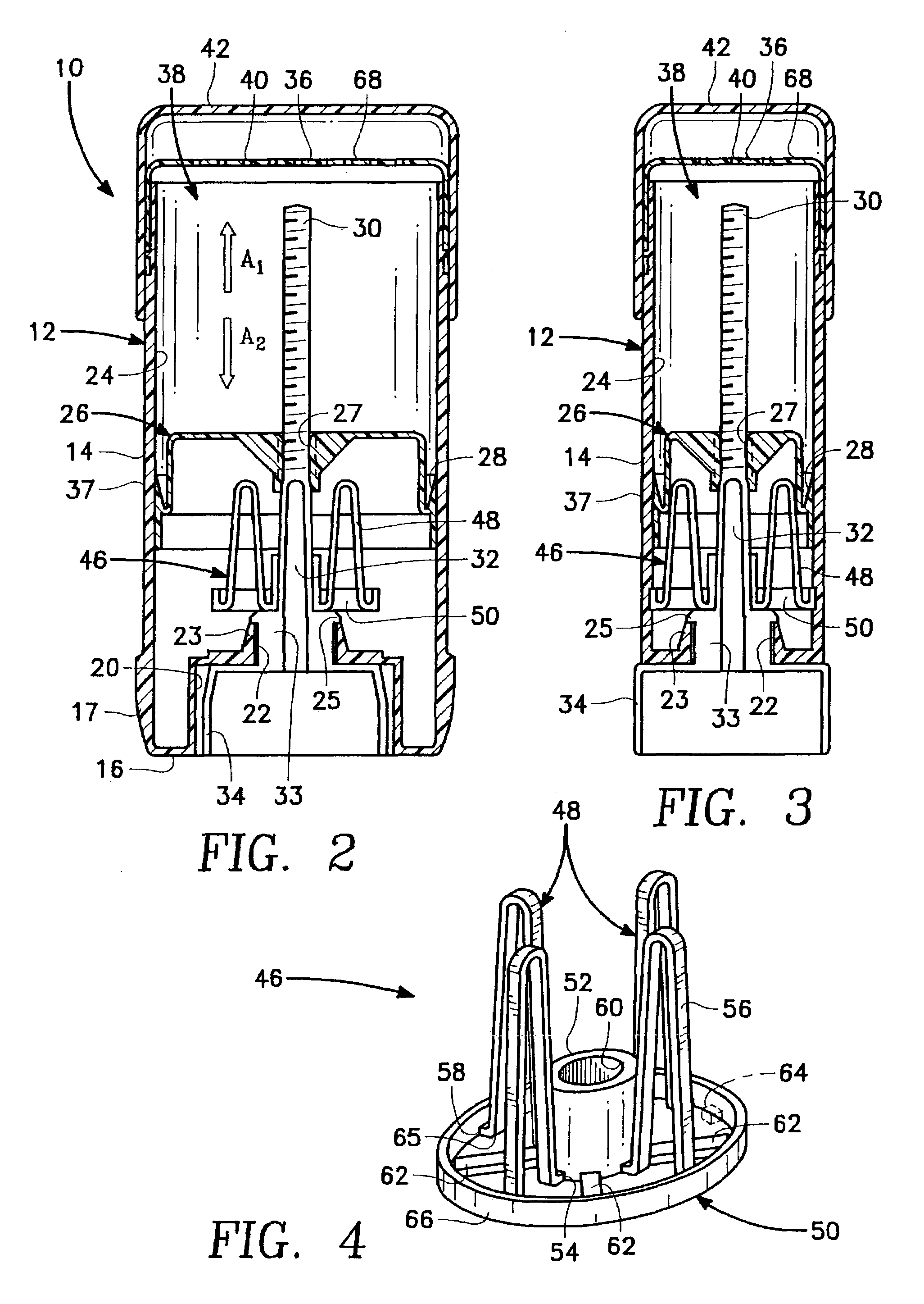
[0028]Referring now to the Figures, the product dispenser is shown and is generally designated by reference character 10. The dispenser comprises a container 12 with a continuous sidewall 14 that extends upwardly from a bottom 16 and terminates at a top opening 18. Bottom 16 further includes a bottom recess 20 and a bottom opening 22 that is formed in the bottom recess 20, as shown in FIGS. 1–3. Preferably, the container should have an oval shaped profile when viewed in top plan, as best seen in FIGS. 5–7. It will be appreciated, however, that square, rectangular or other polygonal profiles (as viewed in top plan) are also envisioned. However, the container should have an interior surface 24 which allows for frictional engagement with other components of the dispenser, as described more fully below.

[0029]The dispenser of the present invention includes an integrated elevator assembly comprising a screw 30 that extends longitudinally within the container and along the geometrical cent...


PUM


Abstract

A dispensing device comprising a container with product outlets, a screw that operates a piston within the container and a torsion spring that biases the screw. The torsion spring includes a hoop having one or more inner tabs. The hoop is frictionally engaged with an interior surface of the container. A boss is fixed to the screw and a flexible arm interconnects the hoop and boss. The torsion spring also includes a spoke that is angularly offset from the flexible arm. Application of a rotational force to the screw urges the piston toward the container outlets, causing the flexible arm to yield, allowing the boss to rotate relative to the hoop until the spoke engages an inner tab. Further rotation releases the hoop from frictional engagement with the container. Once the rotational force is removed, the hoop re-engages the container interior surface and the flexible arm regains its original shape, causing the hub and screw to counter-rotate, which simultaneously moves the piston away from the fluid outlets.

Description

BACKGROUND OF THE INVENTION[0001]1. Field of the Invention[0002]The present invention pertains generally to viscous product dispensing systems. More particularly, the invention pertains to product dispensers that eliminate residual product leakage from the dispenser (commonly known as the “drool effect”) after the actual amount of product that is desired by the user has been dispensed. Additionally, the invention relieves residual pressure within the dispenser which helps reduce product degradation caused by ingredient separation.[0003]2. Description of Related Art[0004]Systems for dispensing viscous flowable materials such as soft-solid deodorant / antiperspirant products, are well-known in the prior art. Typically, the product is extruded out of a container via a plurality of openings that are located at the top of the container. To do this, a chamber in the interior of a dispenser is loaded with the desired product. The product is supported by an underlying structure, such as a pla...

Claims


Application Information

Patent Timeline
Patent Type & Authority Patents(United States)
IPC IPC(8): A45D40/02A45D40/04A45D40/08A45D40/26B65D83/00
CPCA45D40/26B65D83/0011A45D40/08A45D2040/105A45D2200/055
Inventor SPATZ, WALTER B.COCHRAN, MONROE A.HAGER, JEFFREY J.
Owner SPATZ LAB
Why Eureka
Try Eureka