Premixed combustion gas burner having separated fire hole units

a combustion gas burner and premixed technology, which is applied in the direction of burners, combustion types, combustion processes, etc., can solve the problems of increasing the loss of heat due to high-temperature exhaust gas, the need for more than a theoretical amount of air, and the increase of pollutants, so as to prevent deformation and easily change the size and number of fire hole units , the effect of easy change of the total capacity of the burner

Inactive Publication Date: 2005-07-19
KYUNGDONG NAVIEN
View PDF8 Cites 12 Cited by
  • Summary
  • Abstract
  • Description
  • Claims
  • Application Information

AI Technical Summary

Benefits of technology

[0016]To solve the above problems, it is an object of the present invention to provide a premixed combustion gas burner having separated fire hole units, in which a total number of fire hole units formed on the surface of the burner are separated into several pieces, to thereby prevent deformation due to thermal expansion, and easily change the size and number of the fire hole units to easily change a total capacity of the burner.

Problems solved by technology

However, the Bunsen gas burner has a long flame and a high flame temperature, thus needs more that an theoretical amount of air.
Accordingly, there is an increase loss of heat due to high-temperature exhaust gas.
This leads to an increased amount of pollutants such as NOx and CO.
As a result, the Bunsen gas burner is somewhat limited in accomplishing maximum efficiency and reduction of pollutants in the gas burner equipment.
However, in the case where the temperature of flames is low in the conventional premixed combustion gas burner, the burner flames may be unstable.
This may raise the production cost and may make fabrication difficult.
Also, it be difficult to stably control combustion of the premixed gas in home gas burner equipment which has a simple structure.
Also, in the case that ceramic, stainless steel, or knitted metal fiber mat of porous metal fiber weaving tissue is used as a combustion surface material of the premixed combustion gas slits, a premixer for premixing fuel gas and air may become large and somewhat complicated.
As a result, the air blowing resistance increases due to a loss of pressure in the premixer and thus either abnormal noise may occur as part of a high-load region during combustion or main flames of the gas burner may be unstable.
Thereby, fire hole units are formed largely locally or in whole on the metal fiber, and thus cause scattering of the flames, which may cause flames to lack uniformity and a backfire to occur.
Additionally, the conventional premixed combustion gas burner is expensive and difficult to fabricate.
In particular, the conventional premixed combustion gas burner having a tubular shape has downsides.
Specifically, it is difficult to prevent deformation such as buckling due to either thermal tension at the time of an excessive running of the burner, damage by a fire of the burner surface due to overheat, or excessive production of nitrogen oxide due to heal.
Also, the conventional premixed combustion gas burner has a problem that it is difficult to mount a separate device such as a cooling water tube for cooling overheat of the burner.

Method used


Image

  • Premixed combustion gas burner having separated fire hole units
  • Premixed combustion gas burner having separated fire hole units
  • Premixed combustion gas burner having separated fire hole units

Examples


Embodiment Construction

[0028]A premixed combustion gas burner having separated fire hole units according to a preferred embodiment of the present invention will be described below with reference to the accompanying drawings.

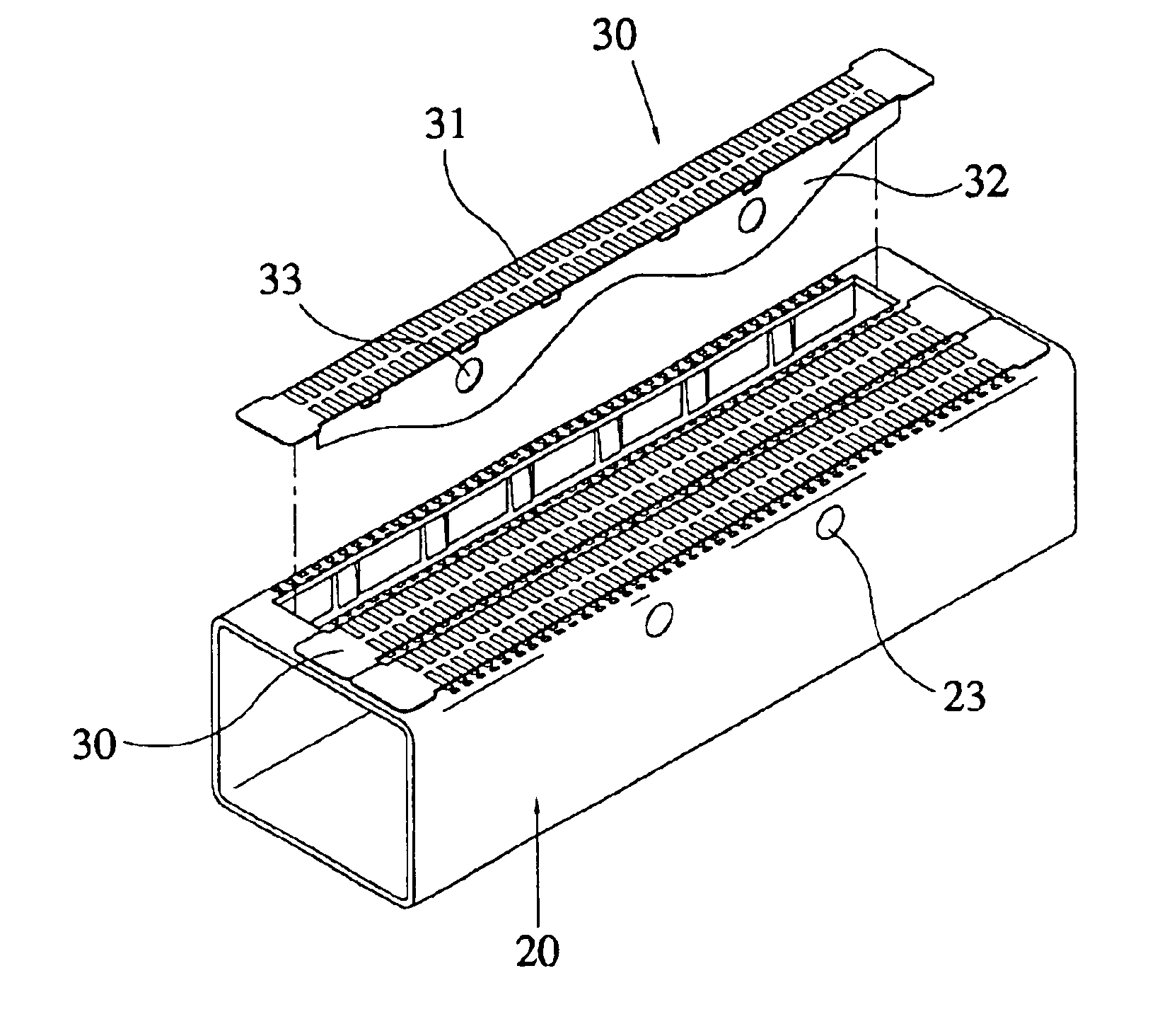
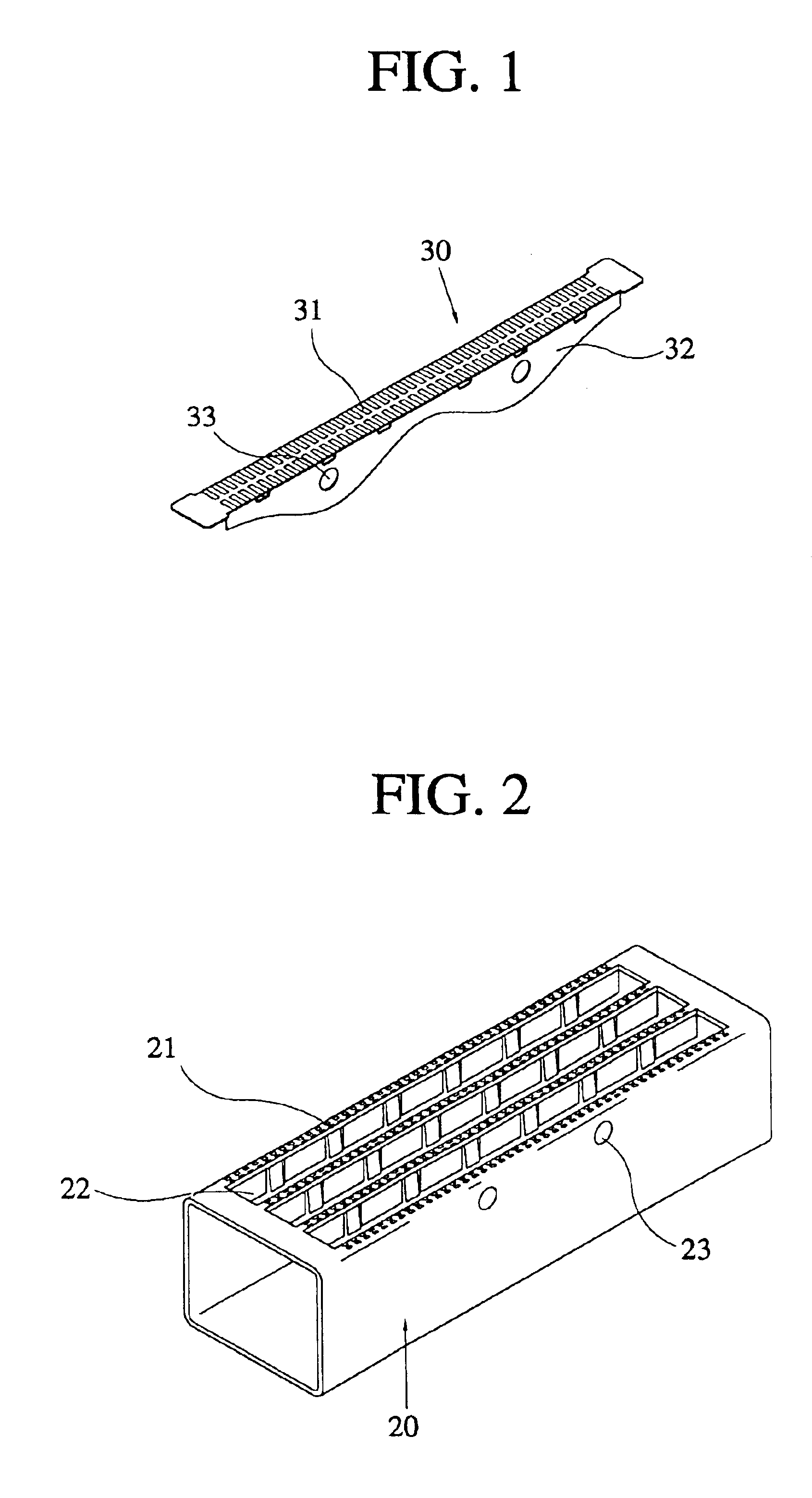
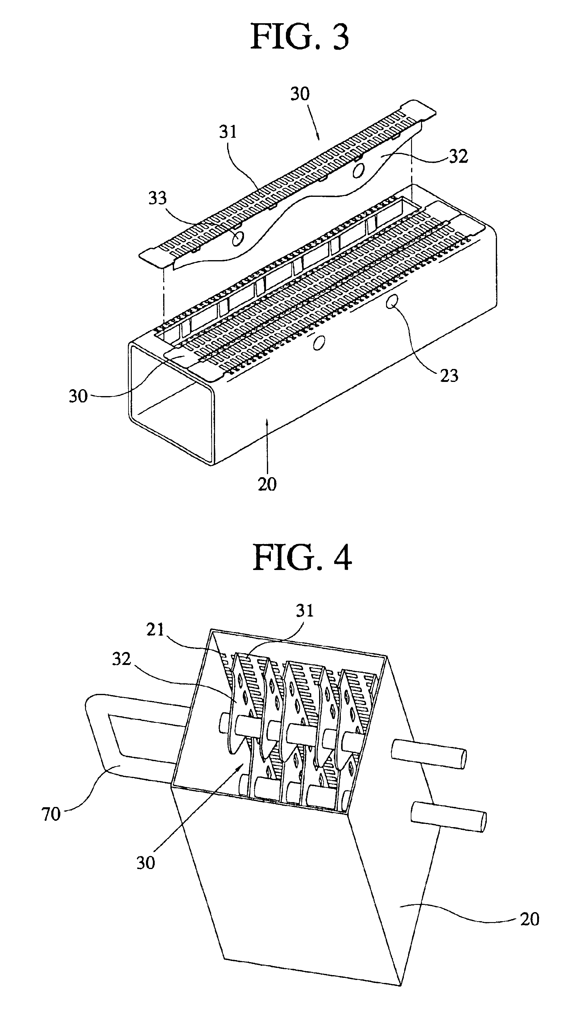
[0029]Referring to FIGS. 1 through 3, a premixed combustion gas burner having separated fire hole units includes a tube-shaped burner 20 in which fire hole units 21, each having a number of fire holes formed at a predetermined distance from one another, disposed on the upper end face. These fire holes are for burning gas and air in a mixed state. A plate-shaped burner 30 which is detachably disposed in loaders 22 is formed between the fire hole units 21 formed on the upper end of the tube-shaped burner 20. The fire hole units 31 have a number of fire holes are disposed.

[0030]As shown in FIG. 1, in the tube-shaped burner 20, according to the present invention, having a front face opened and an inner portion of a hollow tubular shape, fire hole units 21, each having a number of fire hole...


PUM


Abstract

A premixed combustion gas burner having separated fire hole units including a tube-shaped burner whose front face is opened and inner portion is of a hollow tubular shape so that the whole fire hole units of the burner can be separated to thus prevent deformation due to thermal expansion, in which fire hole units each having a number of fire holes formed at a predetermined distance from one another are disposed in both edge lines and the inner portion on the upper end face, and loaders each having a predetermined space are formed between the fire hole units; and a plate-shaped burner which is made of a plate-shaped material having a pin structure formed on the bottom thereof so as to be mounted on the loaders formed in the tube-shaped burner, in which fire hole units having a number of fire holes formed at a predetermined distance are disposed in the form of a slit along both the edge lines of the upper end face. Here, the number of fire holes forming the fire hole units of the tube-shaped burner and the plate-shaped burner are formed with a uniform size by a press, and a cooling water tube is disposed to penetrate the fire holes through fitting holes formed on the lateral surface of the tube-shaped burner and fitting holes formed on the pin-structure formed on the bottom of the plate-shaped burner, in correspondence to the fitting holes of the tube-shaped burner.

Description

BACKGROUND OF THE INVENTION[0001]1. Field of the Invention[0002]The present invention relates to a premixed combustion gas burner having separated fire hole units, and more particularly, to a premixed combustion gas burner having separated fire hole units in which a total number of fire hole units formed on the surface of the burner are separated into several pieces in the premixed combustion gas burner having a tube-shaped burner and a plate-shaped burner which are separated from each other, and a cooling water tube penetrates a pin structure formed on the lower end of the plate-shaped burner, to thereby easily change the size and number of the fire hole units to easily change a total capacity of the burner, prevent deformation of the burner such as buckling due to thermal tension existing in the burner which may be caused by an excessive running of the burner and thermal expansion deformation, and play a role of making the water tube fixing the tube-shaped burner and the plate-sha...

Claims


Application Information

Patent Timeline
Patent Type & Authority Patents(United States)
IPC IPC(8): F23D14/78F23D14/04F23D14/10F23D14/72F23D14/00F23D14/34F23D14/08
CPCF23D14/105F23D14/34F23D14/78F23D2211/00
Inventor CHO, SEUNG BEOMSUN, HEE SUK
Owner KYUNGDONG NAVIEN
Why Eureka
Try Eureka