Method of laser welding a flexible circuit board with a metal contact

a flexible circuit board and metal contact technology, applied in the direction of printed circuit manufacturing, printed circuit non-printed electric components association, manufacturing tools, etc., can solve the problems of insufficient conductor strip material available for a reliable and durable welded connection, circuit boards with access from both sides are much more expensive than circuit boards, and achieve mechanically stable and electrically reliable connection. , the effect of easy operation

Inactive Publication Date: 2005-07-19
CONTINENTAL AUTOMOTIVE GMBH
View PDF13 Cites 38 Cited by
  • Summary
  • Abstract
  • Description
  • Claims
  • Application Information

AI Technical Summary

Benefits of technology

[0007]The invention is based on the object of providing a method for producing an electrical connection between a flexible circuit board and a metallic contact partner which can be carried out easily and at low cost and at the same time realizes a mechanically stable and electrically dependable connection. In particular, it is intended for the connecting point created by means of the method also be suitable for contacting electrical components under aggravated ambient conditions, as prevail, for example, in a gearbox or an engine of a motor vehicle.
[0017]Investigations carried out within the scope of the invention show that, with customary films of plastic used in circuit board fabrication (for example polyimide film) and when using an Nd:YAG laser (wavelength 1.06 μm), the laser light penetrates the film of plastic (second insulating layer) with virtually no energy loss and any energy absorption only occurs when the light impinges on the conductor strip, realized in particular as a copper layer. In this case, the energy introduced during the welding leads to virtually instantaneous melting of the conductor strip and penetration of the laser beam into the region where the contact partner comes to bear. The depth of penetration of the laser beam into the contact partner is an important factor for the quality of the connection formed by the welding operation. If the laser beam is not able to penetrate into the contact partner, i.e. if only the conductor strip is melted, a satisfactory welding result is not achieved. If, on the other hand, the laser beam penetrates into the contact partner, an effect which is referred to as a deep-weld effect occurs. This consists in that the material of the contact partner is instantaneously melted and a more or less eruptive behavior of the metal melt is observed. The eruptive behavior leads to melted material of the contact partner splashing away, the material loss in the central region of the contact partner causing a depression to form. As a consequence of the formation of the depression, an annular welded region is obtained, which is undesired because, depending on the size of the ring opening, part of the available welding area remains unused. The method according to the invention is therefore preferably carried out in such a way that a deep-weld effect optimizing the quality of the welded connection is achieved, which means that, although melting of the surface of the contact partner takes place, splashing away of the metal melt is avoided to the greatest extent or completely. In an ideal case, a full-area (circular disk-shaped) welding region is achieved as a result, although an annular welding region with a comparatively small ring opening can also be tolerated.
[0018]To achieve a deep-weld effect optimizing the quality of the welded connection, the laser is preferably operated in such a way that the melting depth of the surface of the contact partner is between 0.5 and 1 mm.
[0020]A further advantageous measure of the method is characterized in that a number of laser light pulses applied to the second insulating layer in a positionally offset manner are used for creating the welded connection. The positional offset (of the corresponding light spots on the second insulating layer) effectively increases the size of the welding region, which leads to an increase in the strength of the connection.
[0021]An important technical application of the arrangement according to the invention with an electrical connecting point is the contacting of electrical wiring elements or the direct contacting of electrical components which are accommodated together with a control device in an engine or gearbox of a motor vehicle. For such mechatronic control systems there has recently been developed a technical concept in which an electronic circuit accommodated in the control device housing is connected to electrical wiring elements by means of a flexible circuit board that is led to the outside through a sealing gap in the housing or directly to terminal pins of sensors and / or actuators located in the gearbox or engine. For this technology, the arrangement according to the invention provides a suitable and low-cost possibility for electrical contacting between the elements referred to, the welded connection provided being surprisingly so resistant that it is able to withstand the ambient conditions prevailing in a gearbox or engine (temperature range from about −40° C. to 150° C., vibrations up to about 40 g).

Problems solved by technology

However, for practical applications it is disadvantageous that laser welds can currently only be carried out on circuit boards with access from both sides.
In the case of this method, it is problematical that, on account of the central hole, occasionally there is not adequate conductor strip material available for a dependable and durable welded connection.
However, even in the case of this method there must be access to the conductor strip from both sides.
A disadvantage of this is that circuit boards with access from both sides are much more expensive than circuit boards of comparable size and type with access from one side.

Method used


Image

  • Method of laser welding a flexible circuit board with a metal contact
  • Method of laser welding a flexible circuit board with a metal contact
  • Method of laser welding a flexible circuit board with a metal contact

Examples


Embodiment Construction

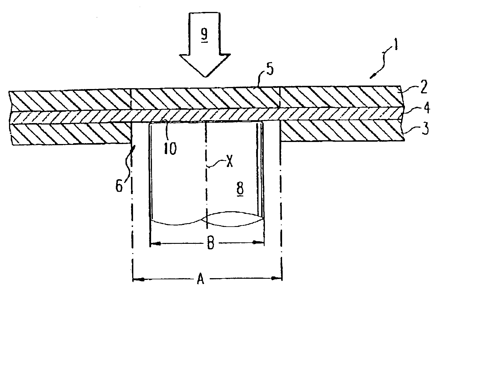
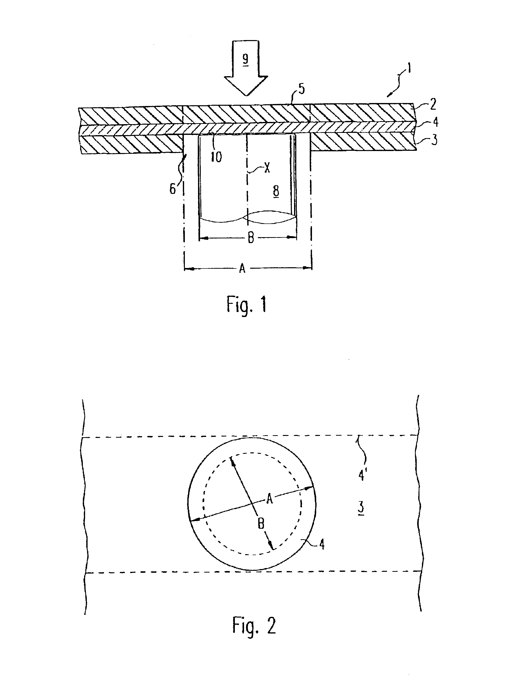
[0027]According to FIG. 1, a flexible circuit board 1 comprises a first insulating layer 3 and a second insulating layer 2, between which a conductor strip 4 is embedded.

[0028]The conductor strip 4 may consist, for example, of Cu; the insulating layers 2, 3 may comprise films of plastic commonly used in circuit board fabrication, such as polyimide films for example, and have a thickness of about 25 or else 50 μm. Depending on the type of circuit board 1, there may be an acrylic or epoxy resin adhesive between the conductor strip 4 and the insulating layers 2, 3 in a way not represented.

[0029]In the first insulating layer 3, an access opening 6 is formed. The corresponding region 5 in the second insulating layer 2, lying opposite the access opening 6, is intact, i.e. the conductor strip 4 is completely covered by the second insulating layer 2 in the region of the contact point to be fabricated on the side facing away from the access opening 6.

[0030]Flexible circuit boards of this typ...


PUM

PropertyMeasurementUnit
melting depthaaaaaaaaaa
average poweraaaaaaaaaa

Abstract

A method for producing an electrical circuit between a flexible circuit board (1) is described, with single-sided access and a metallic contact partner (8), such that the contact partner (8) reaches the metallic conductor strip (4) of the circuit board (1) through an access opening (6) in the unit. The circuit board (1) is thus irradiated with laser light (9) in a region opposite the access opening (6) causing a welded connection between the contact partner (8) and the conductor strip (4) to be formed.

Description

CROSS REFERENCE TO RELATED APPLICATION[0001]This application is a continuation of copending International Application No. PCT / DE01 / 02638 filed Jul. 13, 2001, which designates the United States, and claims priority to German application number 10036900.6 filed Jul. 28, 2000.BACKGROUND OF THE INVENTION[0002]The invention relates to a method for producing an electrical connection between a flexible circuit board with single-sided access and a metallic contact partner, to an arrangement of the elements referred to with an electrical connecting point realized between them and to a module for complete installation in an engine or a gearbox of a motor vehicle, which uses such an electrical connecting point.[0003]It is already known to use laser welding methods for realizing an electrically conducting connection between a flexible circuit board and a metallic conductor. Benefits in principle of this technology are that no additional parts, such as rivets for example, are required for creati...

Claims


Application Information

Patent Timeline
Patent Type & Authority Patents(United States)
IPC IPC(8): H01R43/02H05K3/32H05K1/18
CPCH01R43/0221H05K3/328H01R12/592H01L2224/48091H01L2224/48227H01L2924/00014H05K1/118H05K1/189H05K3/3447H05K2203/107
Inventor FRANZEN, FRANKHAUPT, DETLEFLOIBL, JOSEF
Owner CONTINENTAL AUTOMOTIVE GMBH
Why Eureka
Try Eureka