Magnetic transducer, thin film magnetic head, method of manufacturing magnetic transducer and method of manufacturing thin film magnetic head

a technology of magnetic transducer and magnetic head, which is applied in the direction of manufacturing head surface, magnetic body, instruments, etc., can solve the problems of increasing resistance change rate and method problems, and achieve good thermal stability

Inactive Publication Date: 2005-07-19
TDK CORPARATION
View PDF11 Cites 2 Cited by
  • Summary
  • Abstract
  • Description
  • Claims
  • Application Information

AI Technical Summary

Benefits of technology

[0012]The invention is designed to overcome the foregoing problem. It is an object of the invention to provide a magnetic transducer having good thermal stability, a thin film magnetic head, a method of manufacturing a magnetic transducer and a method of manufacturing a thin film magnetic head.

Problems solved by technology

However, the above-mentioned method may be unable to obtain a satisfactory result of thermal stability although the method can increase the rate of resistance change.
The method has a problem, particularly in the case in which the interlayer is provided in the ferromagnetic layer.

Method used


Image

  • Magnetic transducer, thin film magnetic head, method of manufacturing magnetic transducer and method of manufacturing thin film magnetic head
  • Magnetic transducer, thin film magnetic head, method of manufacturing magnetic transducer and method of manufacturing thin film magnetic head
  • Magnetic transducer, thin film magnetic head, method of manufacturing magnetic transducer and method of manufacturing thin film magnetic head

Examples


first embodiment

Modification of First Embodiment

[0101]A modification of the first embodiment will be described with reference to FIG. 14.

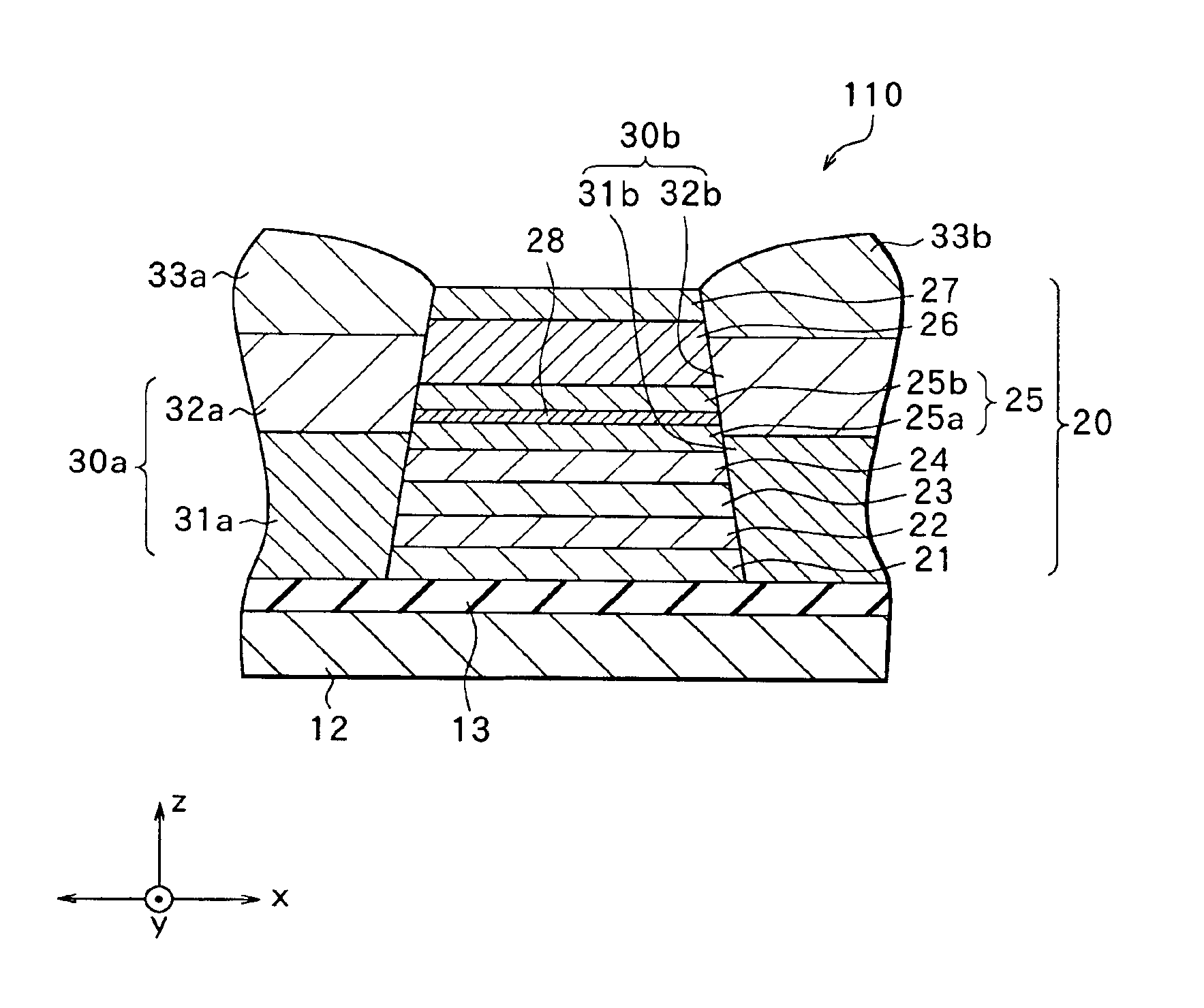
[0102]FIG. 14 shows the structure of the stack 20 of the modification. In the stack 20 of the modification, the interlayer 28 is provided in the ferromagnetic layer 25, and an interlayer 29 is provided in the first soft magnetic layer 22. In the stack 20, the first soft magnetic layer 22 is divided into a bottom layer 22a and a top layer 22b in the direction of stack, and the interlayer 29 corresponding to a specific example of “an interlayer” of the invention is provided between the bottom layer 22a and the top layer 22b, i.e., in the first soft magnetic layer 22. The interlayer 29 has higher electrical resistance than the electrical resistance of the first soft magnetic layer 22 and has magnetism so that the rate of resistance change of the stack 20 may be further increased.

[0103]Preferably, the interlayer 29 contains at least one of, for example, oxide, nitride...

second embodiment

[0106]A second embodiment of the invention will be described with reference to FIG. 15. The second embodiment has the same structure as the first embodiment except that the stack has a different structure. Accordingly, the same structural elements are indicated by the same reference numerals and the detailed description thereof is omitted.

[0107]FIG. 15 shows the structure of a stack 50 of the embodiment. The stack 50 has the same structure as the stack 20 of the first embodiment, except that the interlayer 28 of the first embodiment is replaced by a ferromagnetic interlayer 59 and that an inserted layer 60 is provided adjacent to the ferromagnetic interlayer 59 and close to the antiferromagnetic layer 26. For example, the ferromagnetic interlayer 59 has the same structure as the interlayer 28 except that the ferromagnetic interlayer 59 does not have to contain at least one element in a group consisting of Mn, Cr Ni, Cu, Rh, Ir and Pt.

[0108]The inserted layer 60 is a layer for improv...

examples

[0115]Specific examples of the invention will be described in detail.


PUM

PropertyMeasurementUnit
thicknessaaaaaaaaaa
thicknessaaaaaaaaaa
thicknessaaaaaaaaaa

Abstract

Provided are a magnetic transducer having good thermal stability, a thin film magnetic head, a method of manufacturing a magnetic transducer and a method of manufacturing a thin film magnetic head. A stack of an MR element has a stacked structure comprising an underlayer, a first soft magnetic layer, a second soft magnetic layer, a nonmagnetic layer, a ferromagnetic layer, an antiferromagnetic layer and a capping layer, which are stacked in this order on the underlayer. The ferromagnetic layer is divided into a bottom layer and a top layer in the direction of stack. A ferromagnetic interlayer having magnetism and having higher electrical resistance than the electrical resistance of the ferromagnetic layer is formed between the bottom layer and the top layer. The ferromagnetic interlayer magnetically integrates the bottom layer with the top layer and limits a path for electrons moving through the stack, thereby improving the rate of resistance change. Furthermore, the ferromagnetic interlayer contains, as an additive, at least one element in a group consisting of Mn, Cr, Ni, Cu, Rh, Ir and Pt and thus prevents heat deterioration in the stack.

Description

BACKGROUND OF THE INVENTION[0001]1. Field of the Invention[0002]The invention relates to a magnetic transducer, a thin film magnetic head using the same, a method of manufacturing a magnetic transducer and a method of manufacturing a thin film magnetic head. More particularly, the invention relates to a magnetic transducer having good thermal stability, a thin film magnetic head using the same, a method of manufacturing a magnetic transducer and a method of manufacturing a thin film magnetic head.[0003]2. Description of the Related Art[0004]Recently, an improvement in performance of a thin film magnetic head has been sought in accordance with an increase in a surface recording density of a hard disk or the like. A composite thin film magnetic head, which has a stacked structure comprising a reproducing head having a type of magnetic transducer, i.e., a magnetoresistive element (hereinafter referred to as an MR element) and a recording head having an inductive magnetic transducer, is...

Claims


Application Information

Patent Timeline
Patent Type & Authority Patents(United States)
IPC IPC(8): H01F10/00H01F10/32G11B5/31G11B5/127G11B5/21G11B5/39H01F10/08H01F10/30H01F41/18H01L43/08H01L43/12
CPCB82Y25/00G11B5/1276G11B5/21H01F10/3268
Inventor TSUCHIYA, YOSHIHIROARAKI, SATORUSANO, MASASHIUESUGI, TAKUMI
Owner TDK CORPARATION
Why Eureka
Try Eureka