Rocket engine member and a method for manufacturing a rocket engine member

a technology of rocket engine and rocket engine body, which is applied in the field of rocket engine, can solve the problems of increasing heat load, generating large thermal stresses, and not having a sufficiently long service life required by known designs to withstand a large number of operational cycles, and achieves low pressure drop, long cyclic life, and high pressure capacity.

Inactive Publication Date: 2005-07-26
VOLVO AERO CORP
View PDF8 Cites 16 Cited by
  • Summary
  • Abstract
  • Description
  • Claims
  • Application Information

AI Technical Summary

Benefits of technology

[0013]According to the teachings of the invention, a rocket engine member may be manufactured which presents high pressure capacity, and a low pressure drop, a long cyclic life, as well as advantageous area ratio. The manufacturing lead time and cost may also be optimized.

Problems solved by technology

It is a problem to construct cooled wall structures that are capable of containing and accelerating the hot exhaust gas, and also be reliable through a large number of operational cycles.
Known designs do not have a sufficiently long service life required to withstand a large number of operational cycles.
These known systems generate large thermal stresses, including large pressure drops, or present difficulties when needing repair.
When applying the expander engine cycle, there is a secondary problem.
Increase in the heat load in the combustion chamber due to surface roughness or fins may impair the service life of the engine since the intensity of the heat load is very high in the combustion chamber.
A commensurate increase in the size of the nozzle gives rise to larger nozzles and longer rocket structures, each of which increases the weight of the vehicle.
The joints themselves are weak points that may break and are difficult to repair.
This type of wall structure is not well suited to sustain the tension loads normal in the service life of a rocket nozzle.
The constant section tubes result in a large pressure drop that is not favorable for convectively cooled engines.

Method used


Image

  • Rocket engine member and a method for manufacturing a rocket engine member
  • Rocket engine member and a method for manufacturing a rocket engine member
  • Rocket engine member and a method for manufacturing a rocket engine member

Examples


Embodiment Construction

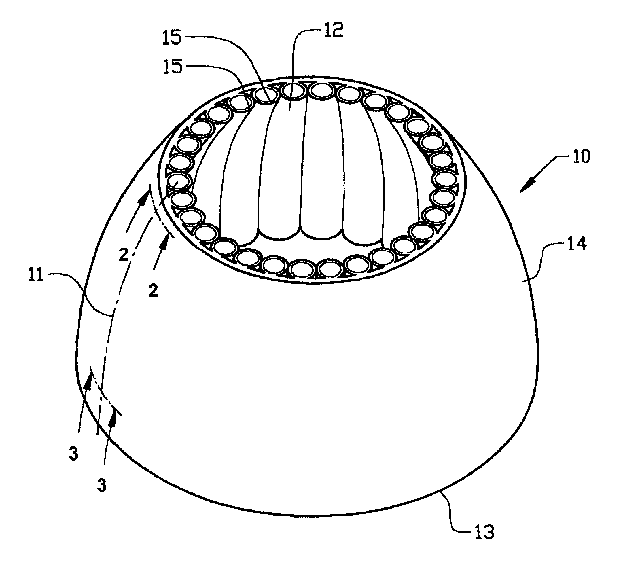
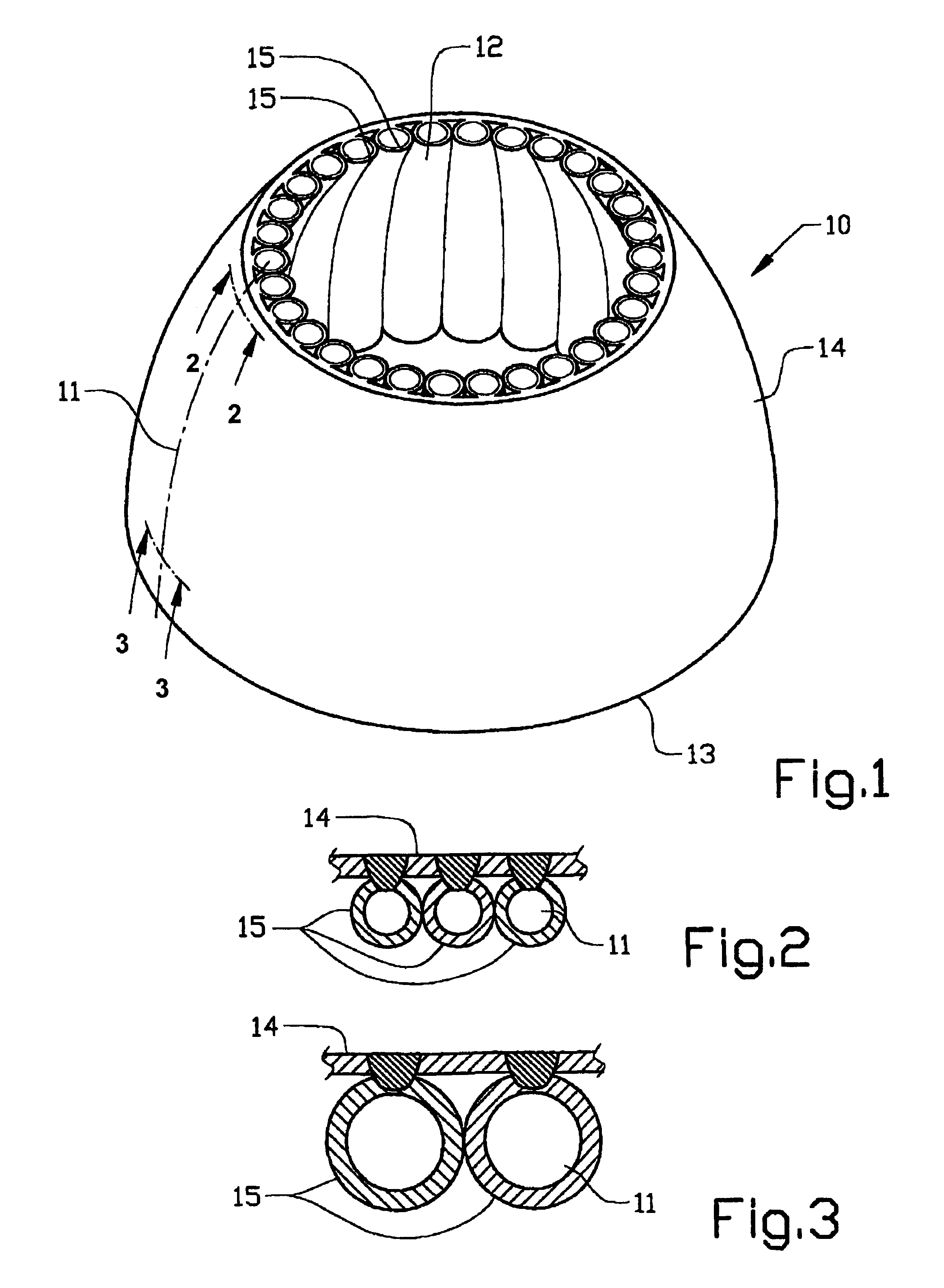
[0024]FIG. 1 shows a diagrammatic and somewhat simplified perspective view of an outlet nozzle 10 that is produced according to the teachings of the present invention(s). The nozzle is intended for use in rocket engines of the type using liquid fuel, for example liquid hydrogen. The working of such a rocket engine is conventional and therefore not described in detail. The nozzle 10 is cooled with the aid of a cooling medium that is preferably also used as fuel in the particular rocket engine. The invention is, however, not limited to rocket engine members of this type, but can also be used in combustion chambers and in those cases in which the cooling medium is dumped after it has been used for cooling.

[0025]The outlet nozzle is manufactured with an outer shape that is substantially bell-shaped. Thus, the nozzle 10 forms a body of revolution having an axis of revolution and a cross section that varies in diameter along said axis.

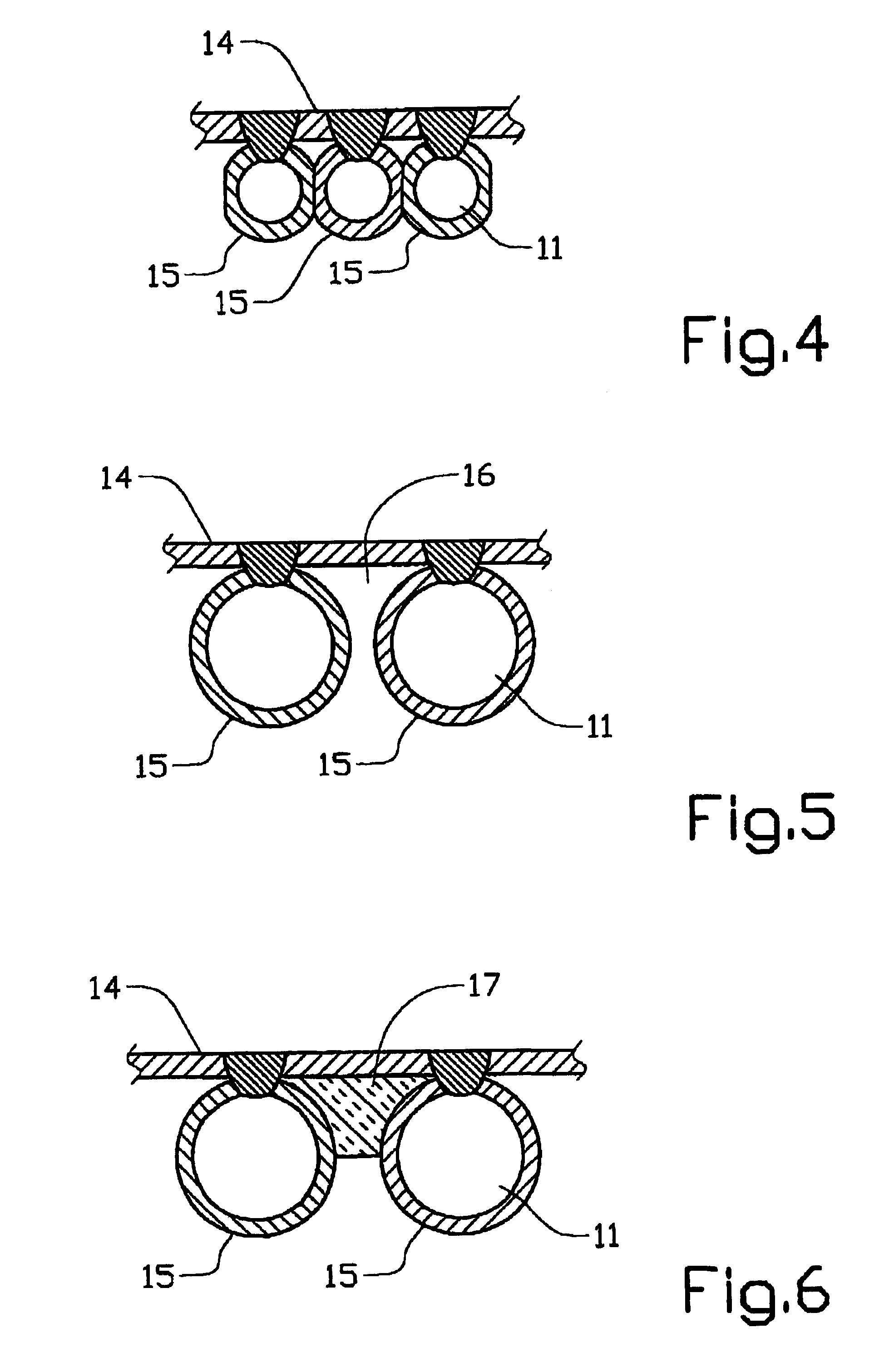
[0026]The nozzle wall is a structure comprising (inclu...


PUM

PropertyMeasurementUnit
temperatureaaaaaaaaaa
diameteraaaaaaaaaa

Abstract

Method and arrangement for providing liquid fuel rocket engine member (10). The member forms a body of revolution having an axis of revolution and a cross section that varies in diameter along said axis. The wall structure includes a plurality of cooling channels (11). The outside of the wall structure includes a continuous sheet metal wall (14). The cooling channels (11) are longitudinally attached to the inside of the sheet metal wall. The method for manufacturing the rocket engine member (10) includes the steps of forming a sheet metal wall (14) having a wall section corresponding to the desired nozzle section, providing a plurality of channel members (15), and attaching the channel members (15) to the inside of the sheet metal wall (14).

Description

CROSS REFERENCE TO RELATED APPLICATIONS[0001]This application is a continuation patent application of International Application No. PCT / SE02 / 00026 filed 9 Jan. 2002 which was published in English pursuant to Article 21(2) of the Patent Cooperation Treaty, and which claims priority to Swedish Application No. 0100079-3 filed 11 Jan. 2001 and to U.S. Provisional Application No. 60 / 261,044 filed 11 Jan. 2001. Said applications are expressly incorporated herein by reference in their entireties.BACKGROUND OF INVENTION[0002]1. Technical Field[0003]The present invention relates to a rocket engine.[0004]2. Background of the Invention[0005]During operation, a rocket combustion chamber or a rocket engine nozzle is subjected to very high stresses, for example in the form of a very high temperature on its inside (on the order of magnitude of 980° F.) and a very low temperature on its outside (on the order of magnitude of −370° F.). As a result of this high thermal load, stringent requirements ar...

Claims


Application Information

Patent Timeline
Patent Type & Authority Patents(United States)
IPC IPC(8): F02K9/64F02K9/48F02K9/00F02K1/00F02K9/97
CPCF02K9/48F02K9/64Y10T29/49428Y10T29/49346F05D2230/232
Inventor HAGGANDER, JANLUNDGREN, JANHALLQVIST, MATS
Owner VOLVO AERO CORP
Why Eureka
Try Eureka