Production method and device for composite tube of butt welding metal tube and polymer

A production method and technology of a production device, which are applied in the field of composite pipes, can solve problems such as the weak composite of polymer and metal pipes, etc.

Inactive Publication Date: 2007-05-16
甘国工
View PDF2 Cites 8 Cited by
  • Summary
  • Abstract
  • Description
  • Claims
  • Application Information

AI Technical Summary

Problems solved by technology

[0007] Scheme 5, Shi Zhen applied for the 99112221 patent "device for manufacturing metal skeleton plastic composite pipe". Its polymer is only designed as a single material, and the polymer extrusion composite mechanism is extruded from the outside of the metal pipe (reinforced skeleton) through its holes into the inner wall of the metal pipe (reinforced skeleton) through the cross die to compound and cover the skele

Method used


Image

  • Production method and device for composite tube of butt welding metal tube and polymer
  • Production method and device for composite tube of butt welding metal tube and polymer
  • Production method and device for composite tube of butt welding metal tube and polymer

Examples


Embodiment 1

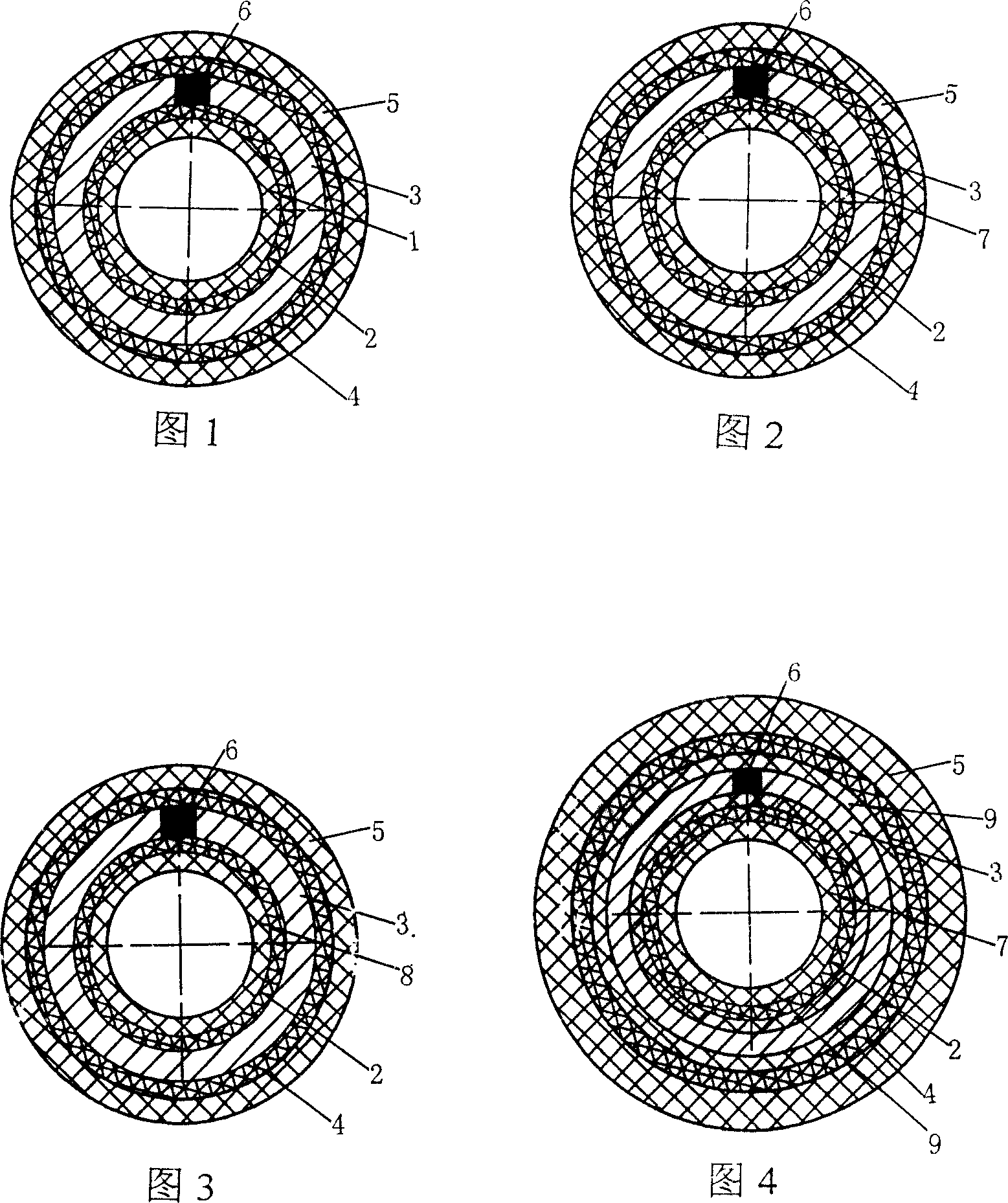
[0050] Fig. 1-Fig. 7 has provided the figure of embodiment 1 of the present invention. Fig. 1 is a schematic structural view of a 5-layer steel-plastic composite pipe produced by the production method and device of the present invention, which are respectively inner layer polyethylene 1, inner layer adhesive layer 2, cylindrical metal pipe-steel pipe 3 from the inside to the outside , the outer adhesive layer 4, the outer polyethylene 5, and the steel pipe 3 has a butt weld 6. Also can adopt cross-linked polyethylene inner layer 7 as shown in Figure 2 inner layer. Also can adopt inner layer 8 of copolymerization polypropylene as shown in Figure 3. Alternatively, as shown in FIG. 4, the inner layer is made of cross-linked polyethylene inner layer 7, and at the same time, an oxygen barrier and anti-corrosion epoxy resin layer 9 is added on the inner and outer surfaces of the steel pipe.

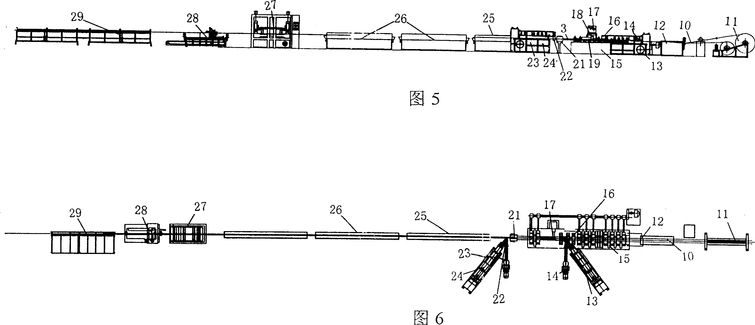
[0051] Referring to Fig. 5 and Fig. 6, an unwinding machine 11 for steel strip 10, a butt...

Embodiment 2

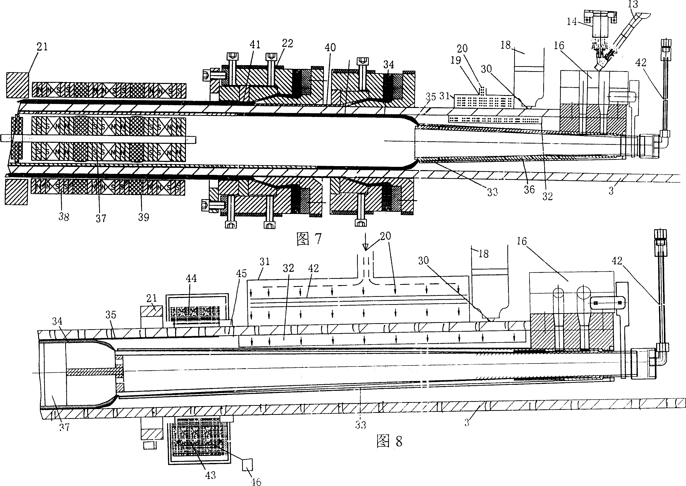
[0054] Fig. 5, Fig. 6, Fig. 8 have provided embodiment 2 figure of the present invention. Embodiment 2 is basically the same as Embodiment 1. The difference is that as shown in Figure 8, the adhesive layer 35 on the inner and outer surfaces of the cylindrical metal frame is to pass the adhesive powder 44 through the orifice on the cylindrical frame 3 through the electrostatic powder spraying device 43 arranged on the outer periphery of the metal cylindrical frame. 45 is formed on the inner and outer surfaces of the cylindrical metal skeleton, and the electrostatic generator 46 makes the electrostatically charged binder powder 44 adhere to the inner and outer surfaces of the metal skeleton more evenly and firmly. After the electrostatic powder spraying device 43, a cylindrical skeleton heater is arranged 21. The thickness of the binder can be increased so that the binder can better melt and coat the skeleton. At the same time, the preheating ability of the skeleton can be incre...

Embodiment 3

[0056] Fig. 5, Fig. 6, Fig. 9 have provided embodiment 3 figure of the present invention. Embodiment 3 is basically the same as Embodiment 1. The difference is that as shown in Figure 6, the extrusion die head 48 extending into the welded cylindrical metal skeleton 3 has a core layer tube 34 extrusion flow channel 50 and an adhesive layer 35 extrusion flow channel respectively. 49. Under the action of the repair ring 51 (or scraper), the adhesive layer 35 extruded earlier will be close to the inner surface of the metal skeleton, and then the core layer tube 34 will be extruded, and the inner sizing rod 47 (or plugged ) under the action, the core tube 34 is compounded on the inner surface of the metal skeleton through the adhesive layer 35. The step-by-step method is used to extrude the adhesive layer separately on the inner surface of the metal skeleton, and then extrude the core layer tube on the adhesive layer, which is beneficial to separately adjust the wall thickness and...


PUM


Abstract

The invention relates to a method for producing composite tube that formed by welded metal tube and polymer, wherein it comprises a, longitudinally or screw coiling the metal band into cylinder metal tube, whose joint is connected; b, welding the joints; c, using extruding head to extrude the polymer when the welding seam is cooled, to be coated on the inner wall of metal tube form fusion corn layer; and using the compressed air of extruder to blow the non-cooled corn layer to make it contact the inner wall of metal tube; d, coating adhesive or plating adhesive powder on the outer wall of metal tube, and extruding polymer outer layer above the adhesive, cooling and shaping to obtain the composite tube. The invention also provides a relative device.

Description

Technical field: [0001] The invention relates to a production method of a composite pipe, in particular to a metal pipe such as a steel pipe, an aluminum pipe welded forming and a core pipe and an outer pipe formed by extruding a polymer on the inner and outer walls of the pipe. The invention relates to a production method and a device for forming a composite pipe composed of a metal pipe and a polymer compounded by a binder and a metal pipe. Background technique: [0002] Metal strips, such as steel strips and aluminum strips to form cylindrical pipes and polymers to form composite pipes, have a large number of technical reports and production. Metal strips and formed cylindrical pipes have high strength, but metal pipes are not corrosion-resistant, so For a long time, people have carried out continuous technical development to obtain a metal pipe and a polymer composite pipe by compounding a polymer that is resistant to corrosion and reduces the friction coefficient of flu...

Claims


Application Information

Patent Timeline
IPC IPC(8): B29D23/00B29C47/02B29C47/06B29C47/88B29C47/56B29C47/26B29C47/08B21C37/08B21C47/02B29C48/09B29C48/335
CPCB29C47/26B29C47/065B29C47/064B29C47/0023B29C48/09B29C48/19B29C48/20B29C48/21B29C48/335
Inventor 甘国工
Owner 甘国工
Why Eureka
Try Eureka