Inverted motor for drilling rocks, soils and man-made materials and for re-entry and cleanout of existing wellbores and pipes

a technology of inverter motors and drilling wells, applied in the direction of drilling machines and methods, directional drilling, borehole/well accessories, etc., can solve the problems of fluid “by-pass” capability through the motor to the lead bit/drilling utensils, and the drilling process will be impaired or bound, etc., to achieve the effect of smooth power generation and overall smoothness

Inactive Publication Date: 2005-07-26
REGENCY TECH
View PDF26 Cites 51 Cited by
  • Summary
  • Abstract
  • Description
  • Claims
  • Application Information

AI Technical Summary

Benefits of technology

[0066]Variations in this basic design can be made to allow this motor to be put into positional series, with or without angular offsetting to smooth out power output to the drilling utensil and with either series or parallel fluid flow paths. A general pattern for use in positional series motors is where both inlet and outlet ports are installed in the same common base or common disc (i.e. both input and exhaust) with distinct internal channels for each function directing the fluid flow. This common disc must be screwed or pressed onto the central shaft for sealing and alignment. A variation in this general pattern for series fluid flow paths is where the outlet / exhaust ports of one motor / motor stage becomes the inlet port for the next motor / motor stage in positional series to the first motor / motor stage all with the same (discharge / inlet) disc. This common disc design also allows the angular rotation of the subsequent motor / motor stage relative to the immediate upstream motor / motor stage for overall smoother power generation. This angular offset is accomplished by directionally machining the internal common disc channels such that the exhaust port on one side / face of the disc is offset some angular rotation from the inlet port on the other side / face of the disc.

Problems solved by technology

Should minimum flow rate not be achieved and maintained, the drilling process will be impaired or bound—sometimes with the tubular string and drilling equipment becoming stuck in the well.
Such fluid “by-pass” capability through the motor to the lead bit / drilling utensil, however, is not available to the industry via technology of the contemporary art.
Electric and turbine powered motors can also be used for downhole operations, but are not widely practiced within the contemporary art.
While some fluids can be vented into the drilled hole (void outside of the drill string and tools) before the motor section and, therefore, not get to the bit or motor, the reverse option (i.e. more fluid getting to the bit than going through the motor) is not possible.
Such limitations restrict the use of Moineau motors for highly deviated / directional / curved drilled holes; for pumping acids, bases, solvents and other corrosive fluids; for high pressure and temperature applications; and for high flow rate applications.
Another limitation is the design and maintenance of pressure seals between a rotating and a fixed surface in these rugged conditions, especially at higher pressures.
However, no method is available utilizing technology of the contemporary art to efficiently transmitted high pressure fluids through the contemporary motor section to be delivered at the drill utensil / bit tip as it is rotating.
Again, no mechanism in the contemporary art has been developed to allow use of this advanced drilling technique without the full high-pressure fluid / solid stream passing through the internal motor section(s).
Thus no motor can work independently of the others.
Also, no current design of downhole motors allows power fluid to fully bypass the motor section to obtain higher rates or high-pressured (greater than 5,000 psig) hydraulic fluid at the utensil / tool / bit tip for other uses, such as running other motors in series, hydraulic and abrasive jetting ahead of the bit.
Furthermore, no 
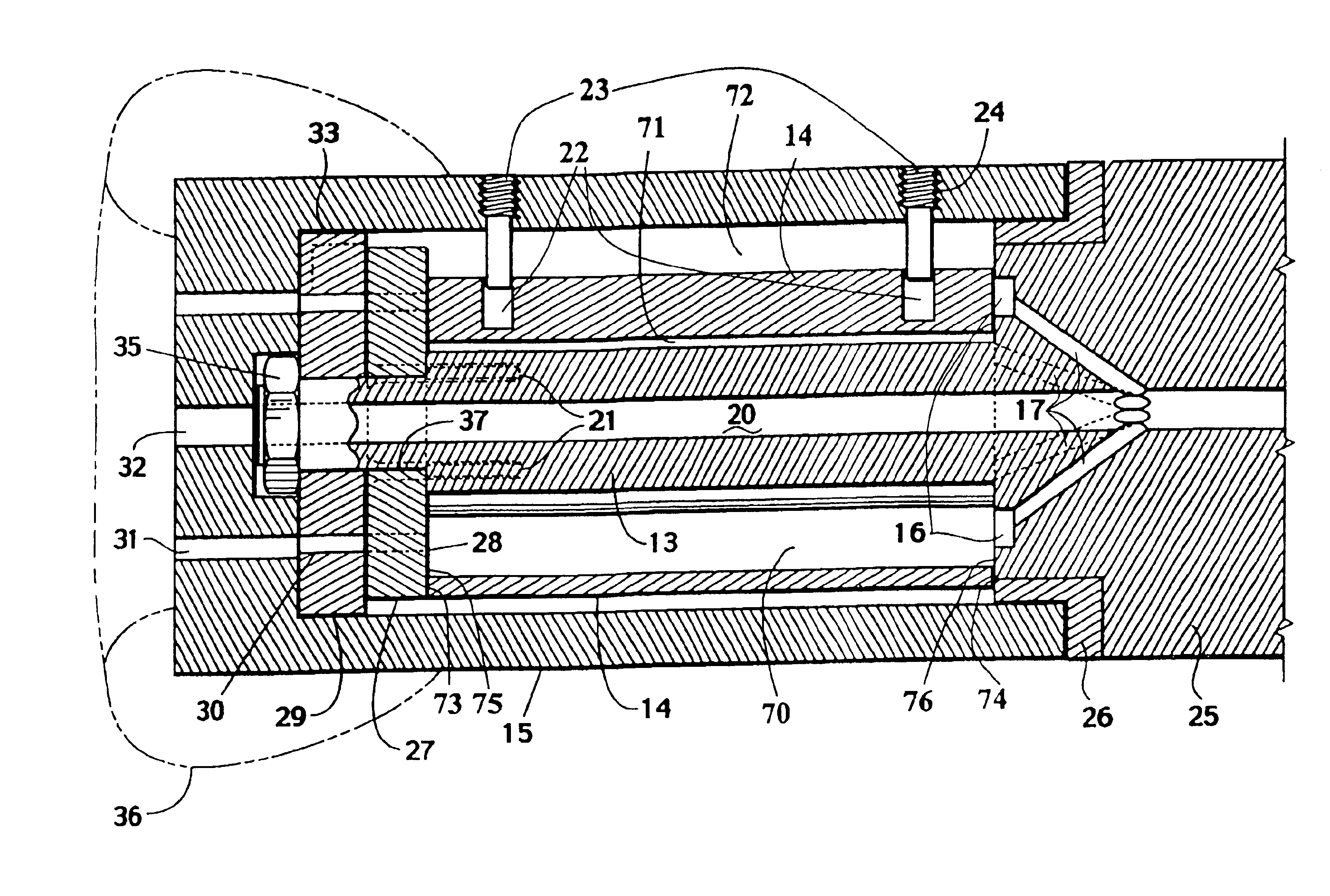
instrumentation can be installed below the motor section, i.e. between the motor and bit, that has hydraulic or electrical communication through the motor section in the contemporary art.
This is due to the disruption of the hydraulic flow path by the motor and the rotating shaft / bit.
This limitation forces all such instrumentation to be above the motor and therefore 30 to 90 feet above / behind the lead bit or drilling utensil.
The same limitations listed immediately above can be said about electrical motors below the initial motor section with limitations on getting the power / communication past the top motor to the subsequent, lower electrical motors.
Electric motors for downhole drilling use are not utilized in contemporary art due to limitations on cooling of the motor components and getting fluid flow to the bit / drilling utensil for cooling, lubrication and bit / hole cleaning.
Additionally, drill rates with conventional methods can be limited by the torque limits of the tubular string and connections.
This limit dictates the size, grade of the materials and the connection type used for the drill string.
There are no means to provide such balancing or reduction of the transmitted torque using conventional techniques, without reduced drilling effectiveness of the drilling process.
The problem of such processes include getting power from the laser / plasma tool to ahead of the bit and / or through the motor section(s) and in keeping the wellbore hole clean of “drilled” materials.
No current method exists to use a downhole motor and / or vibrator immediately above / behind the “bit” with these new processes to breakup the just cooled and solidified displaced drilled materials.
No current method exists to apply a cooling fluid directly ahead of the bit / drilling utensil tip, after thermal spalling / melting / vaporizing, to cool and re-solidify the “drilled” materials for break-up and removal out of the wellbore.
Since it is difficult to have sturdy high-pressure (5000 psi and higher) seal connections across the rotating shaft—non-rotating base junction, operating pressures must be restricted.
Higher pressures within and through the motor to the drill utensils are also limited by these motor seal designs and capabilities.
Increasing temperatures also reduce the available useable pressure, due to reduced materials' strengths.
Most contemporary down-hole motors are limited to about 315 degrees Fahrenheit due to required material selections.
Most contemporary motors, except special designs of the ‘379’ motor, cannot utilize the full range of fluids that the industry has available for use.

Method used


Image

  • Inverted motor for drilling rocks, soils and man-made materials and for re-entry and cleanout of existing wellbores and pipes
  • Inverted motor for drilling rocks, soils and man-made materials and for re-entry and cleanout of existing wellbores and pipes
  • Inverted motor for drilling rocks, soils and man-made materials and for re-entry and cleanout of existing wellbores and pipes

Examples


Embodiment Construction

[0084]FIG. 1 is a simplified longitudinal cross-section drawing of a typical motor currently used in the contemporary art. In this illustration, a motor housing 3 is affixed to and does not move relative to a motor base 1. Said motor base 1 is attached to a hollow tubular drill string. A rotary motor 52 is positioned between said fixed motor housing 3 and a free floating motor shaft 2, causing the shaft 2 to rotate whenever the motor 52 is actuated. A tool / bit 4 is attached to the shaft end 51 that extends out of motor housing 3 and rotates with the shaft 2. Fluid (liquid and / or gas) down flows along path 5 through the internal portion 54 of motor base 1, into a cavity 55 of the rotary motor located between the housing 3 and shaft 2, powering and transversing the motor 52, and crossing over into an interior portion 56 of the motor shaft 2, through a shaft center hole 57 and a tool bit flow channel 58, into a tool bit center hole 59 and exiting via a tool / bit-end opening 53.

[0085]FIG...


PUM


Abstract

An inverted motor with a drilling utensil attached to or integrated as part of an outer motor housing that rotates around a fixed non-rotating shaft or tube. The non-rotating shaft or tube is attached to a fixed base and can extend to the end or past the end of the drilling utensil. A rotary motor is positioned between the outer rotating housing and center fixed shaft and imparts force and motion to the housing and drilling utensil. A channel traverses through the length of the shaft or tube to allow fluids or wires to fully or partially bypass the motor.

Description

REFERENCE TO PENDING APPLICATIONS[0001]This application relates back to provisional application, Ser. No. 60 / 324,866 filed Sep. 27, 2001, and incorporated by reference herein in its entirety.REFERENCE TO MICROFICHE APPENDIX[0002]This application is not referenced in any Microfiche Appendix.[0003]1. Field of the Invention[0004]This invention relates generally to the field of motors utilized in drilling operations of rock, soil, concrete and man-made materials, and, more particularly to inverted motors for drilling rocks, soils, concrete and man-made materials, including the re-entry and clean out of existing wellbores, pipes and pipelines.[0005]2. Background of the Invention[0006]Contemporary art in wellbore related applications utilize a diversely structured hollow tubular string, which extends from one end at the earth's surface to an opposite end at or near the bottom of a wellbore where a cutting bit and related equipment (sometimes and herein referred to synonymously as “drillin...

Claims


Application Information

Patent Timeline
Patent Type & Authority Patents(United States)
IPC IPC(8): E21B4/02E21B4/04E21B4/00
CPCE21B4/003E21B4/02E21B4/04
Inventor OGLESBY, KENNETH D.
Owner REGENCY TECH
Why Eureka
Try Eureka