Illuminating optical system, image display unit and method of illuminating space modulation element

a technology of illumination optical system and image display unit, applied in the field of illumination optical system, can solve the problems of insufficient relative intensity of red light, inability to obtain favorable color rendering properties, and inability to achieve sufficient brightness of projected imag

Inactive Publication Date: 2005-07-26
SONY CORP
View PDF9 Cites 21 Cited by
  • Summary
  • Abstract
  • Description
  • Claims
  • Application Information

AI Technical Summary

Problems solved by technology

However, as shown in FIG. 10, in such a super high pressure mercury lamp, compared to blue light and green light, the relative intensity of red light is considerably insufficient.
Due to the insufficiency of a red light component, the white balance of a projected image finally obtained tends toward green and blue, so favorable color rendering properties cannot be obtained.
However, in such a method, the whole illuminance declines, thereby resulting in the occurrence of such a pro

Method used


Image

  • Illuminating optical system, image display unit and method of illuminating space modulation element
  • Illuminating optical system, image display unit and method of illuminating space modulation element
  • Illuminating optical system, image display unit and method of illuminating space modulation element

Examples


Embodiment Construction

[0026]Preferred embodiments of the present invention are described in more detail below referring to the accompanying drawings.

[0027]At first, referring to FIG. 1, the structure of a liquid crystal display apparatus as an image display apparatus according to an embodiment of the invention will be described below. In the embodiment, “front” means a side closer to a light source when viewed from an object, and “back” means a side opposite to the light source when viewed from the object.

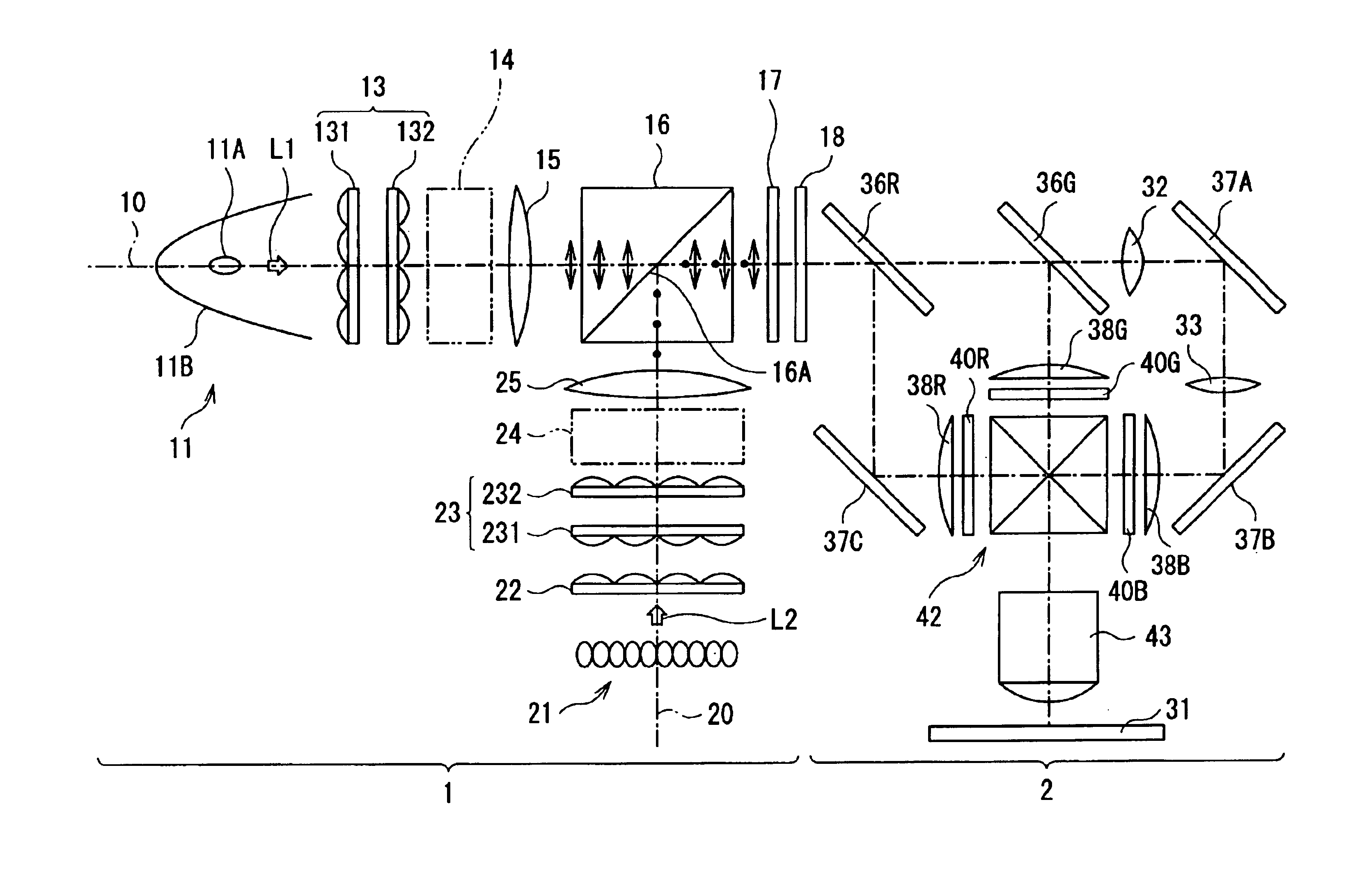
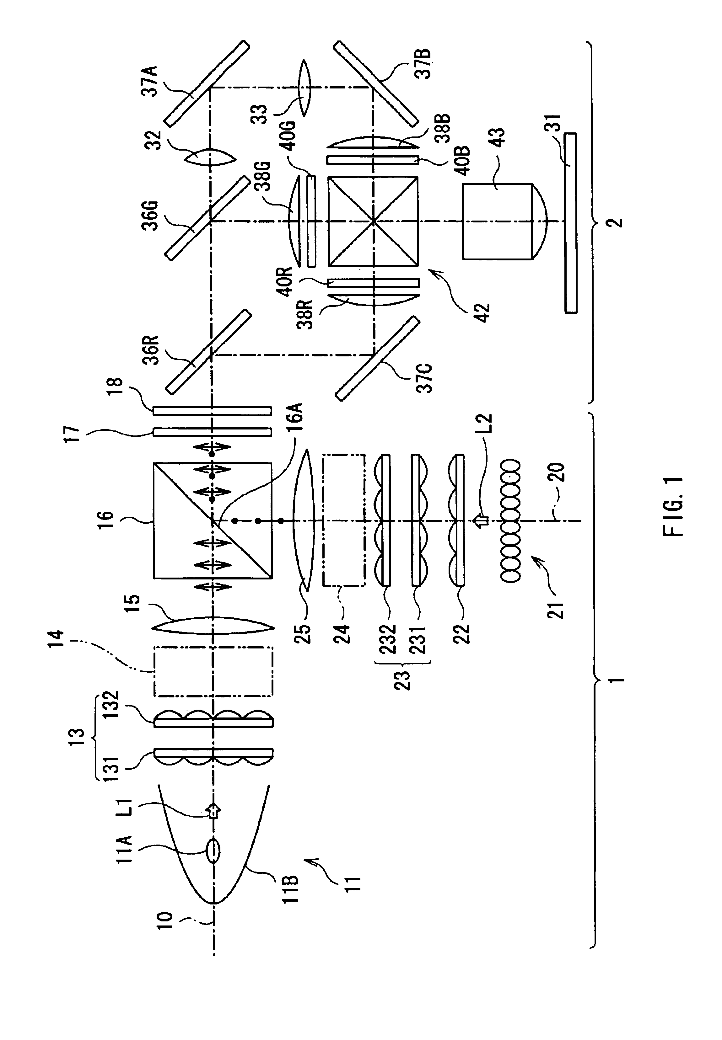
[0028]FIG. 1 shows a schematic view of the liquid crystal display apparatus according to the embodiment when viewed from directly above or side. The liquid crystal display apparatus is a three-panel system projection type color liquid crystal display apparatus, and comprises a first optical system 1 and a second optical system 2.

[0029]The first optical system 1 includes a first light source 11, a second light source 21 and a PS separation / synthesis device 16. A central axis 10 (hereinafter referred to a...


PUM


Abstract

Provided are an illumination optical system having superior color rendering properties while ensuring sufficient illuminance, an image display apparatus comprising the illumination optical system and a spatial modulation device illuminated by the illumination optical system, and a method of illuminating the spatial modulation device. A first light source (11), a second light source (21) having a different emission spectrum from an emission spectrum of the first light source (11), and a replacement optical system replacing light in a specific waveband in a luminous flux (L1) from the first light source (11) with a luminous flux (L2) from the second light source (21) are comprised, and the light in the specific waveband with weak light intensity in the luminous flux (L1) from the first light source (11) is replaced with the luminous flux (L2) with sufficient intensity from the second light source (21). Thereby, a white balance can be kept without reducing the illuminance more than necessary, and superior color rendering properties can be exhibited.

Description

TECHNICAL FIELD[0001]The present invention relates to an illumination optical system for illuminating an object in a balanced manner, an image display apparatus comprising such an illumination optical system and a spatial modulation device illuminated by the illumination optical system, and a method of illuminating such a spatial modulation device.BACKGROUND ART[0002]In recent years, for example, a projection type liquid crystal display apparatus using a spatial modulation device typified by a liquid crystal panel as an optical switching device, and magnifying and projecting an image on the liquid crystal panel on a screen by a projection optical system such as a liquid crystal projector or the like has been widely used. As the liquid crystal display apparatus of this kind, a single-panel system comprising one liquid crystal panel including three color filters of B (blue), R (red) and G (green), and a three-panel system comprising three monochrome liquid crystal panels for optical p...

Claims


Application Information

Patent Timeline
IPC IPC(8): G02B27/00G02B27/28H04N9/31G03B21/20
CPCG02B27/0905G02B27/285H04N9/315G03B21/208G03B21/2073G03B21/2013H04N9/3197G02B27/18G03B21/00
Inventor TOMITA, HIDEOKATSUMATA, MASAOYAMAMOTO, HIDEKI
Owner SONY CORP
Why Eureka
Try Eureka