

Electric connection box
a technology for connecting boxes and electric cables, which is applied in the field of electric connection boxes, can solve the problems of high fabrication cost of connection boxes, high design, construction and assembly waste, etc., and achieve the effects of compact size, reduced fabrication cost, and light weigh
- Summary
- Abstract
- Description
- Claims
- Application Information
AI Technical Summary
Benefits of technology
Problems solved by technology
Method used
Image

Examples
first embodiment
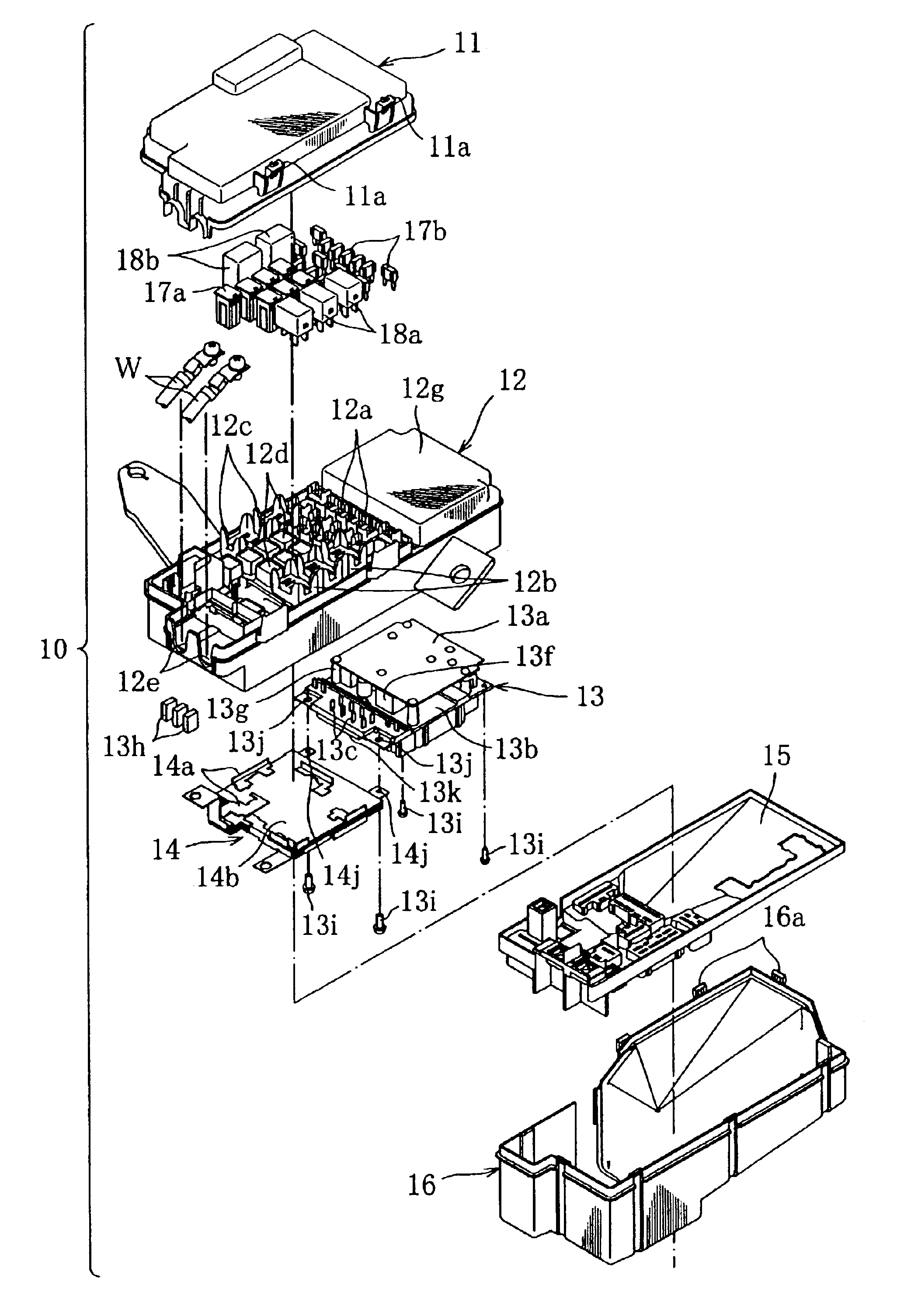
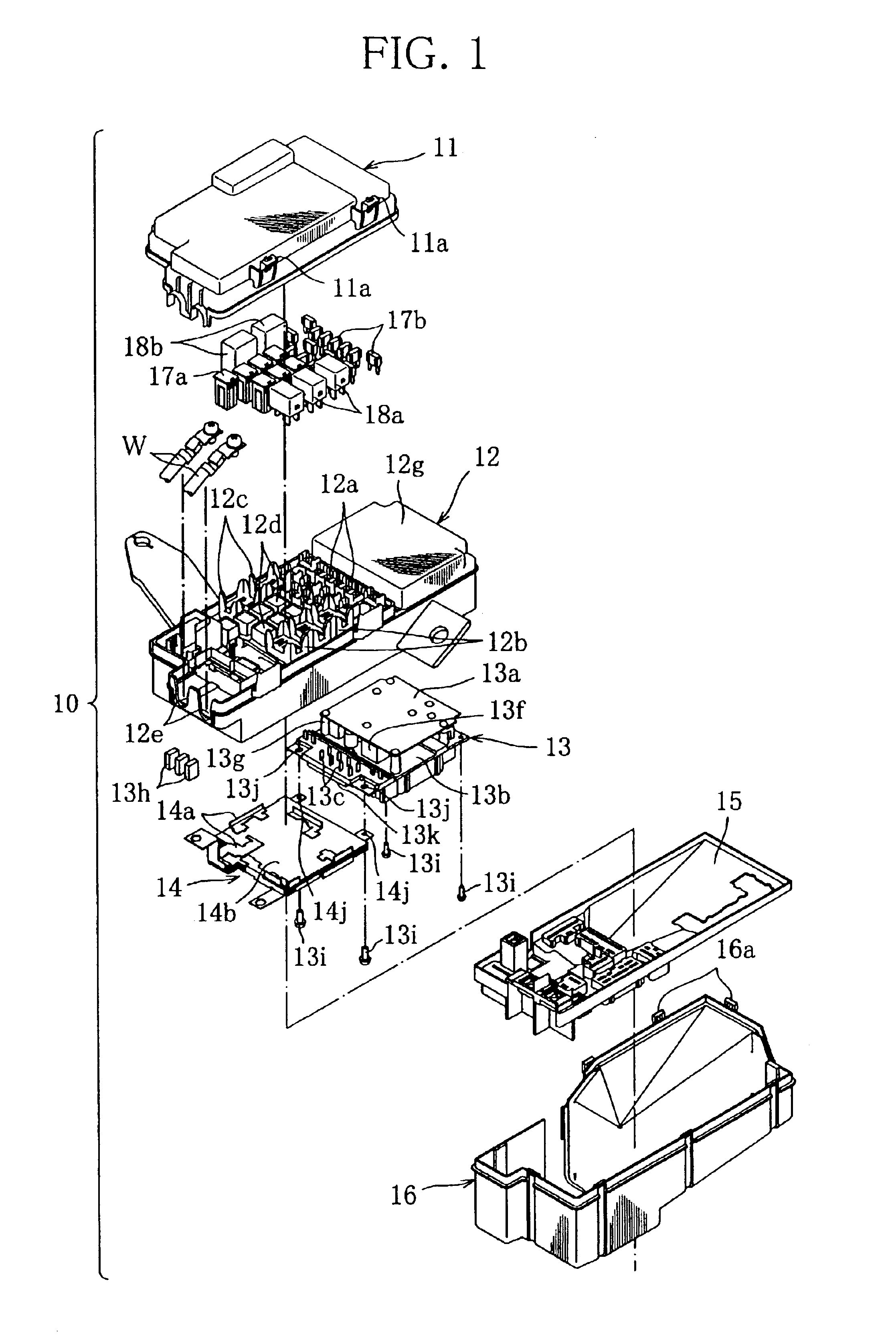
[0016]With reference to FIG. 1, an electric connection box according to the present invention will be explained.
[0017]The electric connection box 10 of this embodiment includes an upper cover 11, an upper case 12, a relay module 13, a bus bar module 14, a lower case 15, a lower cover 16, a fuse group 17a, 17b, and a relay group (first relays) 18a, 18b.
[0018]The upper cover 11 is made of synthetic resin and mounted on the upper case 12 to cover the same, and has engaging portions 11a formed at appropriate positions of side edges of the upper cover.
[0019]The upper case 12 has an upper side thereof formed with housings 12a-12d which are located at appropriate positions and which have appropriate shapes suitable for the mounting of the fuse group 17a, 17b and the relay group 18a, 18b. The upper case 12 has one end thereof formed with projections projecting therefrom in the longitudinal direction. Each projection is formed with a mounting portion 12e which is a recessed groove in which ...
second embodiment
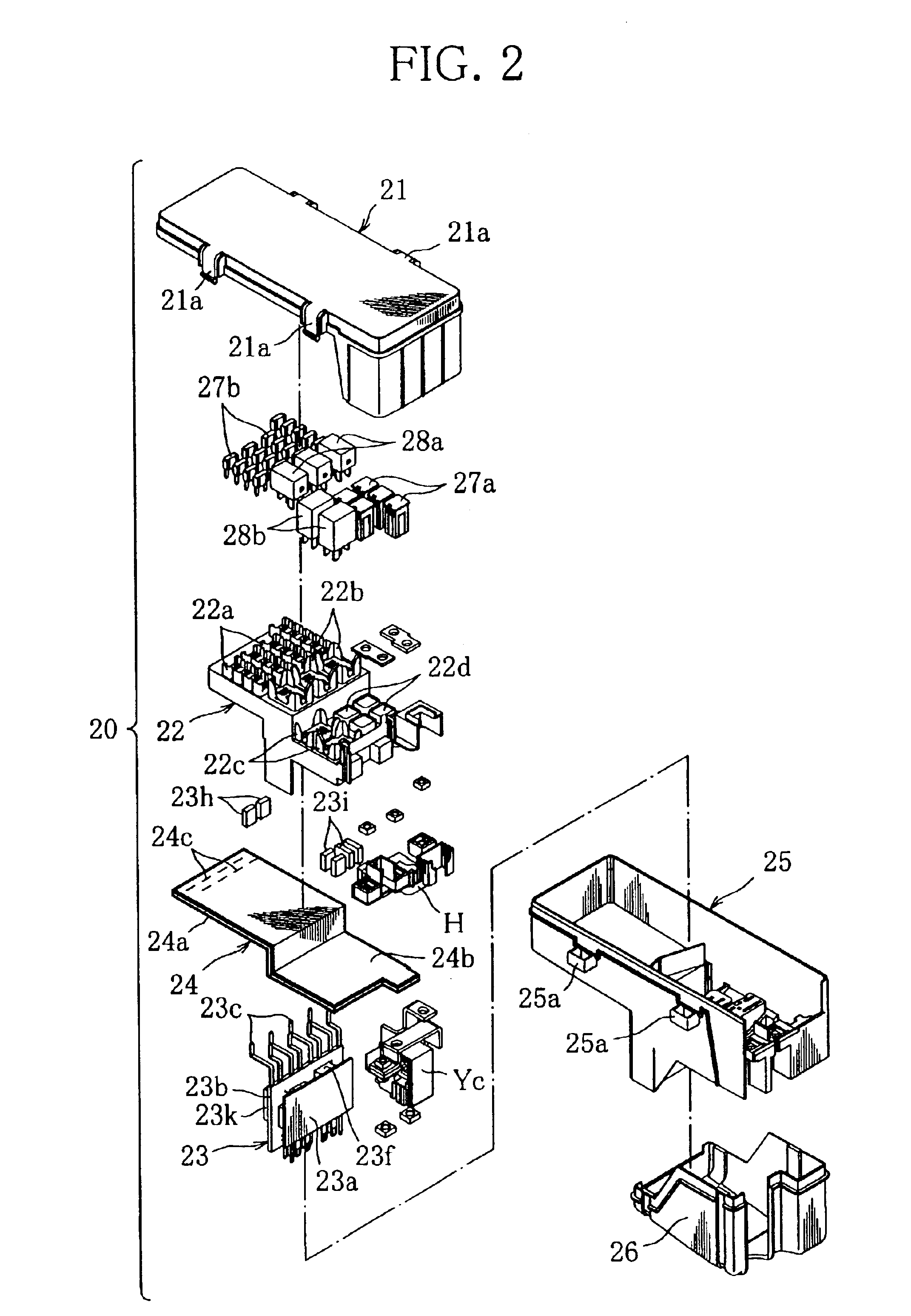
[0030]Next, an electric connection box according to this invention will be explained with reference to FIG. 2.
[0031]In FIG. 2, those elements of the electric connection box 20 of the second embodiment which correspond to like elements of the connection box 10 of the first embodiment are denoted by like numeral (for instance, reference numeral 21, 22, etc. denote elements correspond to elements 11, 12, etc.), and duplicate explanations thereof will be omitted. This applies to third to sixth embodiments.
[0032]As shown in FIG. 2, the electric connection box 20 includes an upper cover 21, an upper case 22, a relay module 23, a bus bar module 24, a holder H, an electric current detecting unit Yc, a lower case 25, a lower cover 26, a fuse group 27a, 27b, and a relay group 28a, 28b.
[0033]The relay module 23 is vertically disposed and provided with a communication control section 23a having a function of controlling multiplex communication, and a power control section 23b operable under th...
third embodiment
[0043]In the following, an electric connection box according to this invention will be explained.
[0044]As compared to the electric connection box 20 of the second embodiment, the electric connection box 30 shown in FIG. 3 differs in the arrangement of the fuse group 27a, 27b and relay group 28a, 28b and in the construction of the upper case 32, relay module 33 and bus bar module 34.
[0045]In association with the altered arrangement of the fuse group 27a, 27b and relay group 28a, 28b, the upper case 32 is formed with housings 32a-32d having appropriate shapes and arrangements suitable for the mounting of the fuse group 27a, 27b and relay group 28a, 28b.
[0046]The relay module 33 is provided with a communication control section 33a and power control sections 33b, 33d whose operations are controlled by the communication control section 33a. The communication control section 33a is disposed above at a distance from the power control section 33b, with spacers (not shown) interposed thereb...
PUM
 Abstract
Description
Claims
Application Information