Automation equipment control system

a control system and automation equipment technology, applied in the direction of programme control, distance measurement, electric programme control, etc., can solve the problems of inability to guarantee the execution of control loops in real-time, the general purpose computer system is not fully successful, and the control loop is not fully reliabl

Inactive Publication Date: 2005-07-26
INTELLECTUAL VENTURES II
View PDF2 Cites 25 Cited by
  • Summary
  • Abstract
  • Description
  • Claims
  • Application Information

AI Technical Summary

Benefits of technology

[0018]Robot control systems of the present invention provide robot control via commercially standard, general purpose computer hardware and software. The control systems and methods acc...

Problems solved by technology

First, robot users seek control systems implemented using commercially available standard computers and operating systems rather than customized proprietary systems.
With respect to the open-systems feature, efforts at delivering a robot control system based on standard, general purpose computer systems have not been fully successful because of the limitations of general purpose operating systems.
The multi-feature design objectives for general purpose operating systems such as Microsoft Windows NT® have yielded very complex, some...

Method used


Image

  • Automation equipment control system
  • Automation equipment control system
  • Automation equipment control system

Examples


Embodiment Construction

[0042]The invention disclosed herein is, of course, susceptible of embodiment in may different forms. Shown in the drawings and described herein below in detail are preferred embodiments of the invention. It is to be understood, however, that the present disclosure is an exemplification of the principles of the invention and do not limit the invention to the illustrated embodiments.

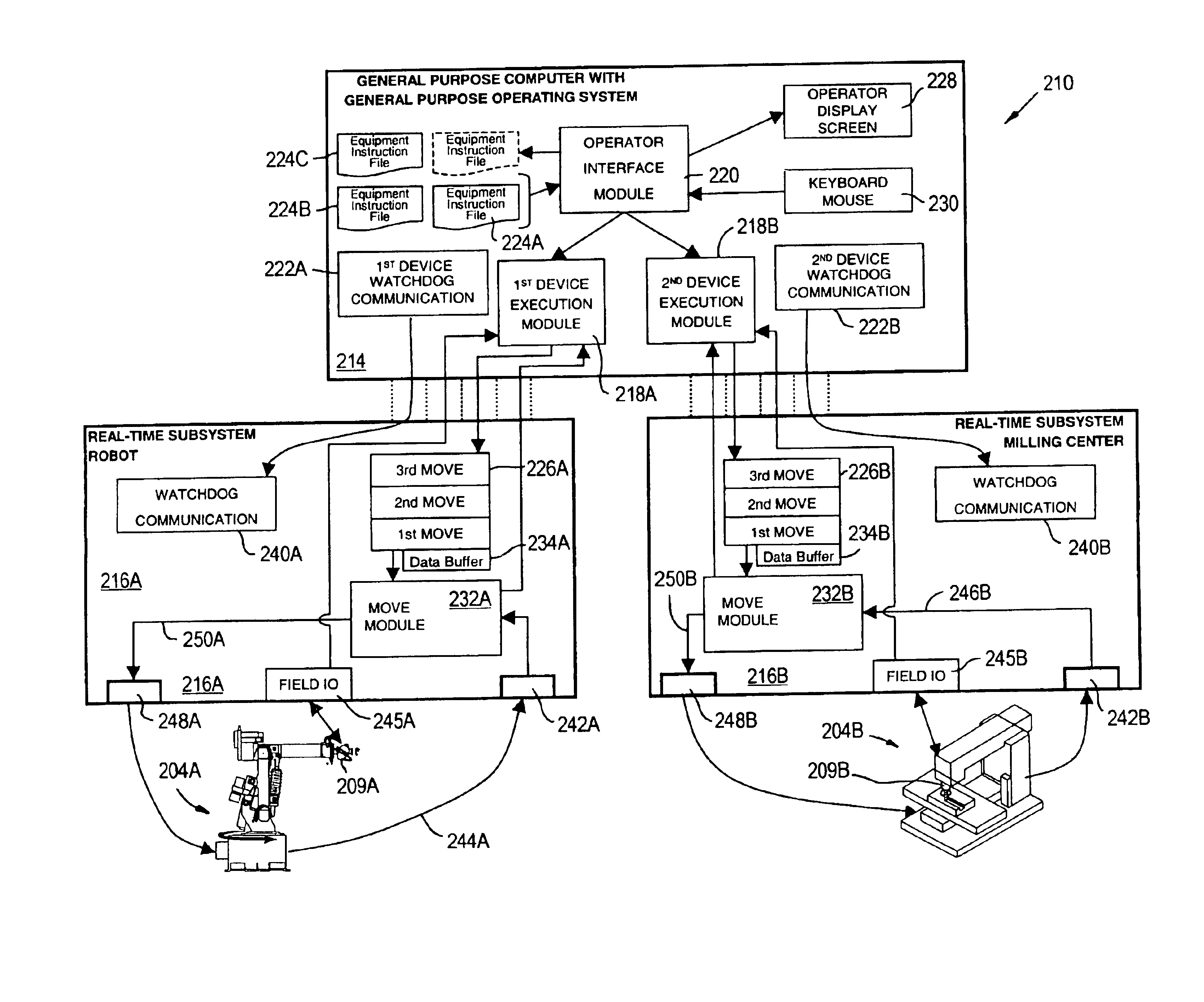
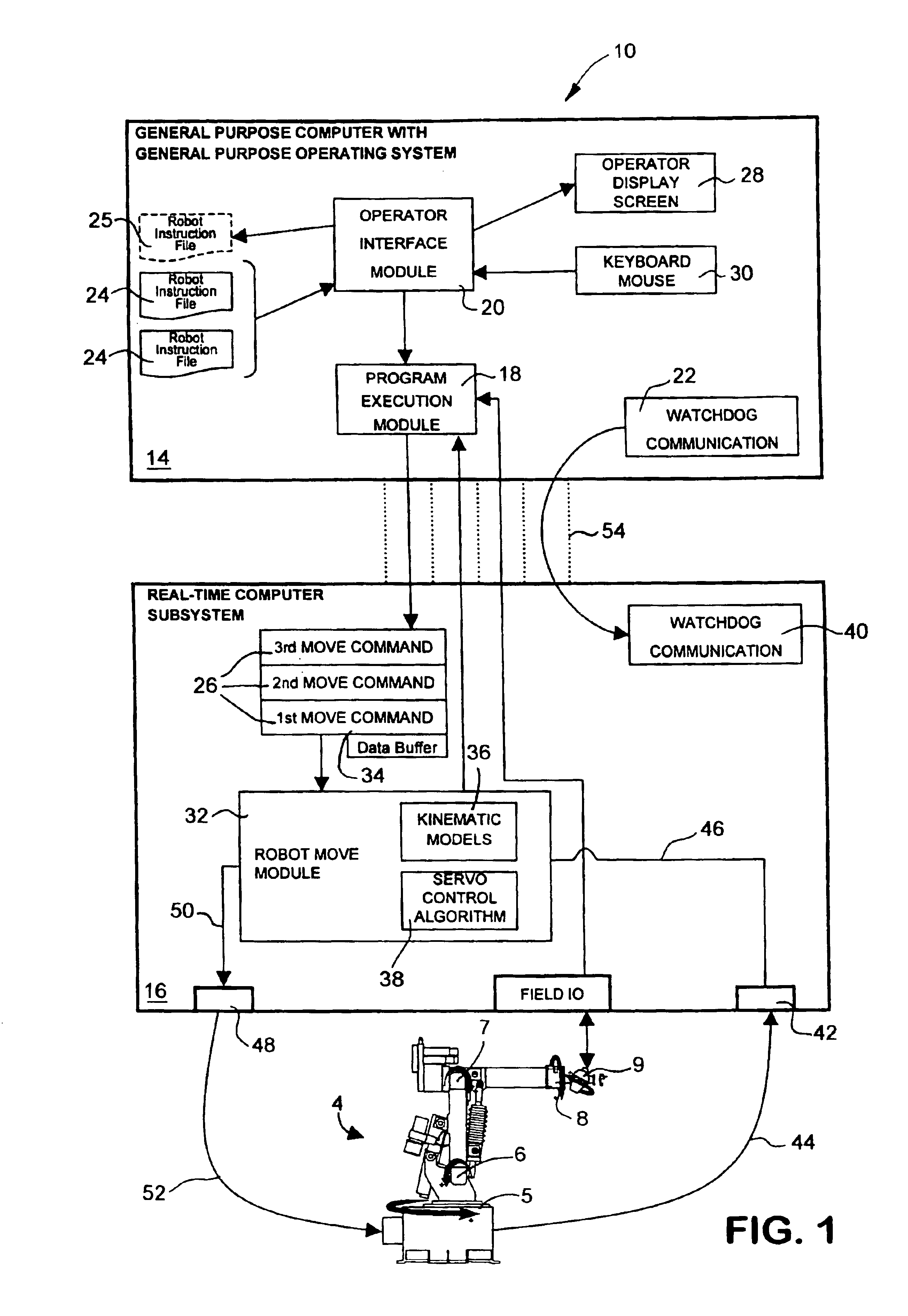
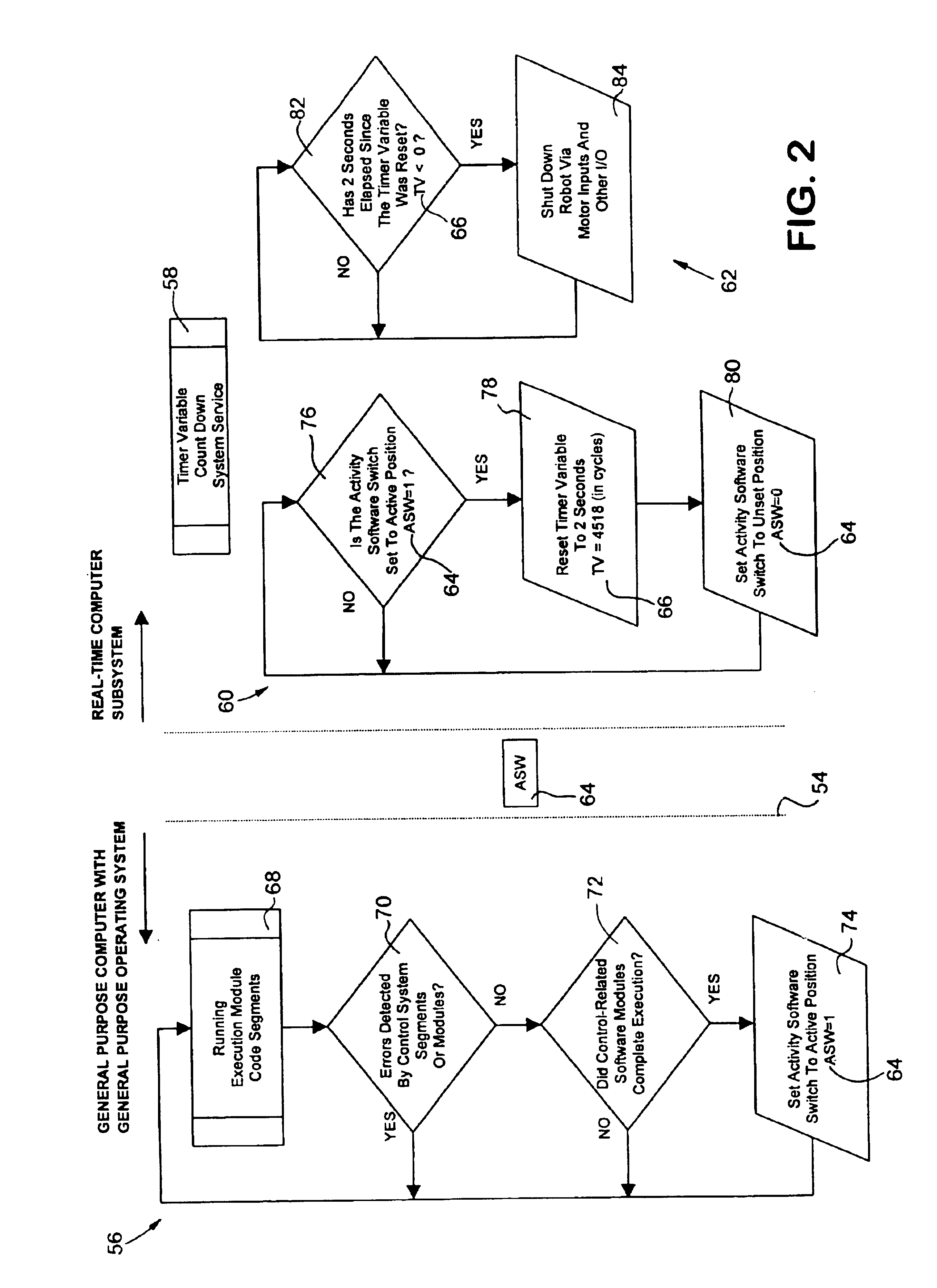
[0043]In the FIGURES, a single block or cell may indicate several individual software and / or hardware components that collectively perform the identified single function. Likewise, a single line may represent several individual signals or several instances of software data sharing or interconnection.

[0044]Robots as well as other manufacturing machines include positioning arms with mechanical joints, positioning actuators such as motors for causing movement about the joints, and position feedback sensors which provide an indication of the position of some part of the robot. Automation equipment other than ...


PUM


Abstract

A automation equipment control system comprises a general purpose computer with a general purpose operating system in electronic communication with a real-time computer subsystem. The general purpose computer includes a program execution module to selectively start and stop processing of a program of equipment instructions and to generate a plurality of move commands. The real-time computer subsystem includes a move command data buffer for storing the plurality of move commands, a move module linked to the data buffer for sequentially processing the moves and calculating a required position for a mechanical joint. The real-time computer subsystem also includes a dynamic control algorithm in software communication with the move module to repeatedly calculate a required actuator activation signal from a joint position feedback signal.

Description

CROSS-REFERENCE TO RELATED APPLICATION[0001]This application is a continuation of U.S. patent application Ser. No. 10 / 227,660, filed on Aug. 26, 2002, now U.S. Pat. No. 6,675,070, which, in turn, is a continuation-in-part of U.S. patent application Ser. No. 09 / 750,433, filed on Dec. 28, 2000, now U.S. Pat. No. 6,442,451.FIELD OF THE INVENTION[0002]This invention relates to an apparatus and method for controlling automation equipment and more particularly, to a versatile control system suitable for controlling automation equipment of various electromechanical configurations.COPYRIGHT NOTIFICATION[0003]Portions of this patent application contain materials that are subject to copyright protection. The copyright owner has no objection to the facsimile reproduction by anyone of the patent document, or the patent disclosure, as it appears in the Patent and Trademark Office.BACKGROUND OF THE INVENTION[0004]Industrial robots and similar highly flexible machine tools gained commercial accept...

Claims


Application Information

Patent Timeline
IPC IPC(8): B25J9/16B25J13/00B25J13/06B25J19/06G05B19/414
CPCB25J9/1656B25J9/161B25J9/1697G06F17/50G05B2219/33242G05B2219/34047G05B2219/34261G05B2219/39001A61B1/00158Y10S901/47Y10S901/46Y10S901/42Y10S901/48A61B1/31A61B1/041A61B1/0055Y10S901/41B25J9/16G06F30/00
Inventor LAPHAM, JOHN R.
Owner INTELLECTUAL VENTURES II
Why Eureka
Try Eureka