Device arrangement structure for hybrid construction equipment

a technology of hybrid construction and device arrangement, which is applied in the direction of fluid couplings, couplings, mechanical machines/dredgers, etc., can solve the problems of deficiency of torque, achieve the effect of reducing the wiring length of the generator motor and the inverter, improving the reliability of the device of the charging system, and reducing the temperature of the temperatur

Active Publication Date: 2005-08-02
KOMATSU LTD
View PDF5 Cites 86 Cited by
  • Summary
  • Abstract
  • Description
  • Claims
  • Application Information

AI Technical Summary

Benefits of technology

[0012]According to the above second constitution, the same operational effects as in the above-described first constitution are obtained. Further, the devices of the charging system are placed separately from the devices of the high pressure hydraulic system, the devices of the charging system are hardly given the influence of the heat from the devices of the high pressure hydraulic system, and the rise in temperature thereof is suppressed, thus making it possible to improve reliability of the devices of the charging system.
[0013]In the device arrangement structure: the inverter may be placed at an upstream side of a fan driven by the engine; and the generator motor may be connected to the engine, at a side near to the inverter. According to this constitution, the generator motor is connected to the end portion of the engine, which is at a side near to the inverter, and therefore the wiring length of the generator motor and the inverter is shortened.
[0014]Consequently, the electrical power loss between them can be made small, and therefore the driving efficiency of the generator motor and the rege

Problems solved by technology

On the other hand, when, for example, the regeneration torque is smaller than the driving torque of the hydraulic pump, only an amount of deficiency of torque which is the result of subtracting t

Method used


Image

  • Device arrangement structure for hybrid construction equipment
  • Device arrangement structure for hybrid construction equipment
  • Device arrangement structure for hybrid construction equipment

Examples


Embodiment Construction

[0019]Preferred embodiments of the present invention will be explained in detail below with reference to the drawings. In the following embodiments, the explanation will be made with a hydraulic shovel being cited as an example of the machine to which the present invention is applied.

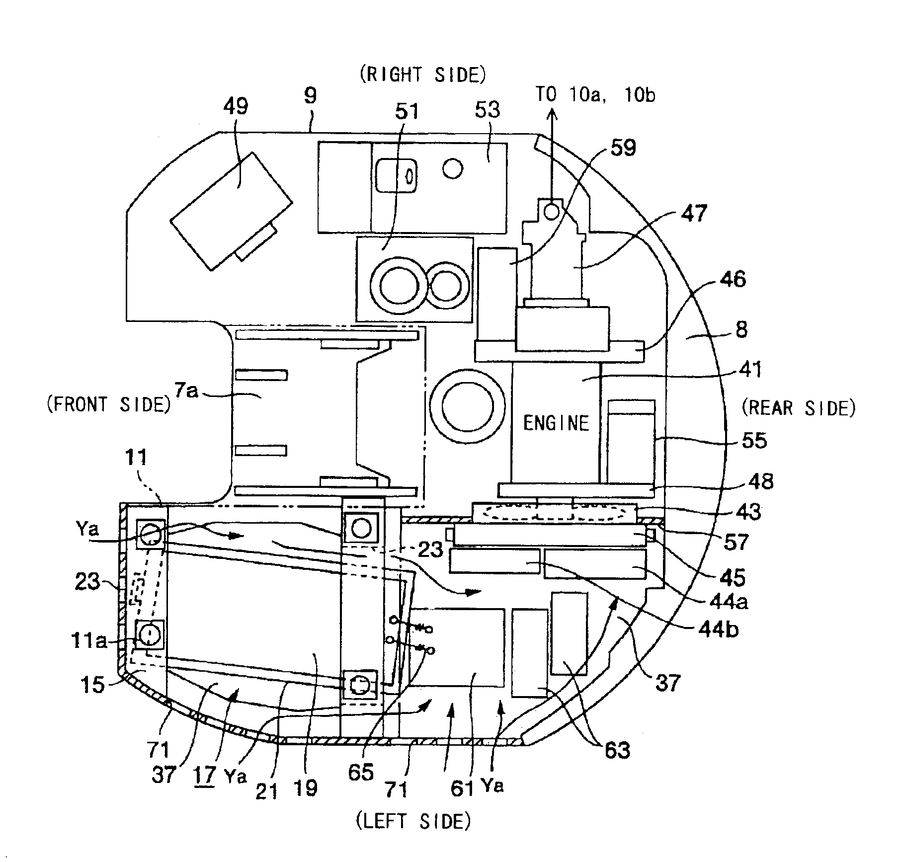
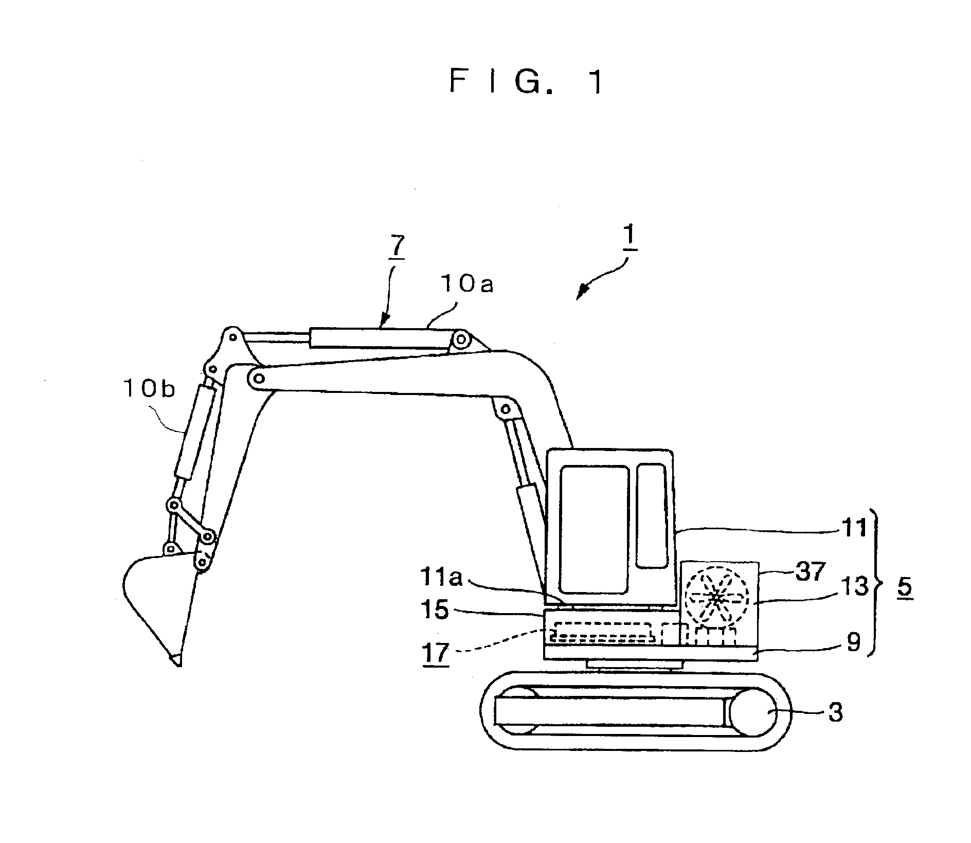
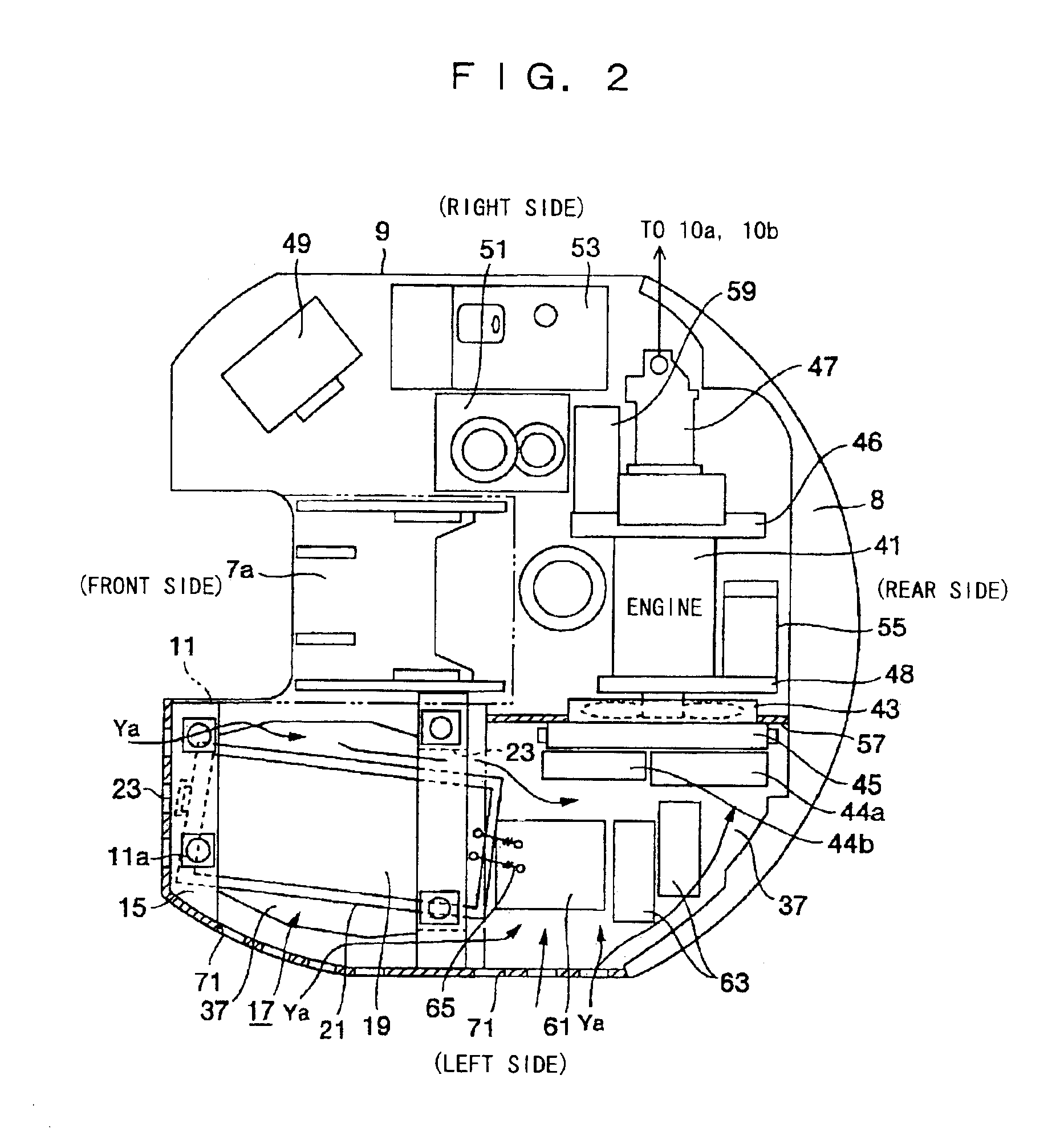
[0020]In FIG. 1 and FIG. 2, a hydraulic shovel 1 is loaded with an upper revolving superstructure 5 rotatably on a top portion of a lower traveling unit 3, and is provided with a working machine 7 for performing an operation such as excavation, for example, at a substantially central portion in a lateral direction of a front part of the upper revolving superstructure 5 to be able to hoist and lower. FIG. 1 shows the case in that a crawler type traveling unit is used as the lower traveling unit 3, but this is not restrictive, and an ordinary lower traveling unit is applicable. A driver's cab 11 is placed at a left front portion of a top portion of a revolving frame 9, which is a base frame of the upper r...


PUM


Abstract

A device arrangement structure for hybrid construction equipment capable of reducing devices of a charging system in size is provided. For this purpose, in the device arrangement structure: a hydraulic pump (47) is connected to an engine (41) via a first power take-off (46); and a regenerative motor (59), which is regenerated by return oil from hydraulic actuators (10a, 10b), and a generator motor (55), which assists an engine as an electric motor to drive hydraulic pump and generates power with surplus torque of the regenerative motor, are provided in parallel with the hydraulic pump via the first power take-off.

Description

TECHNICAL FIELD[0001]The present invention relates to a device arrangement structure for hybrid construction equipment, and it particularly relates to a device arrangement structure for hybrid construction equipment in which a hydraulic pump and a generator motor are connected to an engine.BACKGROUND ART[0002]As for construction equipment such as a conventional hydraulic shovel, a hydraulically driven type, which controls an inflow of pressure oil discharged from a hydraulic pump with an engine as a power source into each hydraulic actuator so as to carry out drive of each kind of working machine, traveling of vehicle, and the like, is generally used. However, operations of a hydraulic shovel include not only the operations which always require 100% capacity of the capacity of the engine (maximum output horse power), but also a number of operations which can be performed with a smaller capacity (of 80%, for example) than them. Consequently, some hydraulic shovels perform a so-called...

Claims


Application Information

Patent Timeline
IPC IPC(8): E02F9/08E02F9/22E02F3/34E02F3/28E02F9/00E02F9/20
CPCE02F3/325E02F9/0866E02F9/2075E02F9/2217B60L2200/40B60L50/15Y02T10/7072E02F9/00
Inventor NARUSE, MASAMIOHTSUKASA, NARITOSHIINOUE, HIROYUKI
Owner KOMATSU LTD
Why Eureka
Try Eureka