Tailed flying wing aircraft

a flying wing and aircraft technology, applied in the field of tailed flying wing aircraft, can solve the problems of reducing reducing the wing span, and limiting the maneuverability of aircraft on the ground, so as to reduce the wing span

Inactive Publication Date: 2005-08-02
DIZDAREVIC FARUK +1
View PDF25 Cites 58 Cited by
  • Summary
  • Abstract
  • Description
  • Claims
  • Application Information

AI Technical Summary

Benefits of technology

[0020]a) Significant reduction of fuel consumption and increase in range and lift capacity when compared to existing large civil and military aircraft based on classical concept.
[0021]b) Significant increase in longitudinal stability and maneuverability, as well as reduction of profile and wave drag at high subsonic speed when compared to concepts of large aircraft that are based on the existing art pertaining to “Flying Wing” concepts.
[0023]1. Provide for higher lift capacity regarding existing large civil and military aircraft by transforming surface area of the fuselage into an airlifting surface.
[0024]2. Significantly reduce parasitic drag of large subsonic aircraft by transforming fuselage into an airlifting surface and smoothly blending it with external wings.
[0026]4. Significantly reduce the length of runways with improved safety during takeoff and at landing for large aircraft based on the classical concept by significantly increasing airlifting surface area and ground effect coupled with very good maneuverability control in all three axes.
[0027]5. Reduce wing span relatively to large aircraft based on classical “Fuselage” and “Flying Wing” concepts, thereby providing for easy maneuver on existing airports.

Problems solved by technology

Increase in air traffic volume and very dynamic development thereof have set very challenging goals with respect to moving ever larger payloads safely at large distances as fast as possible at low cost.
The results of this search did not fully meet market demands so that in the past two to three decades the solutions for reduction of transportation cost have been sought by increasing payload capacity and thereby the external dimensions of aircraft, which resulted in significant increase of parasitic drag of fuselage with wing spans reaching critical size that limits maneuver of aircraft on the ground.
Very complex configuration of these aircraft generates high interference drag between aircraft sections.
Simultaneously, the central section with relatively thick airfoils generates high airfoil drag especially at high flight speed.
However, the aerodynamic efficiency of these aircraft is significantly lower when compared to modern aircraft with classical design concept.
Also, manufacturing costs would be significantly higher for these aircraft.
The basic shortcoming of both of these patents is insufficient longitudinal stability and pitch maneuver.
U.S. Pat. Nos. 2,406,506; 2,412,646 and 2,650,780 show classical “Flying Wing” concepts with short chords, low sweep angle of wings, and thick airfoils in the payload area, which generate high airfoil drag, while relatively low wing sweepback angle does not provide for a sufficient longitudinal stability and pitch maneuver of the aircraft.
Low aspect ratio of the wings results in insufficient roll maneuver and generates high induced drag, which reduces aerodynamic efficiency that was achieved by boundary layer control in the area of jet engines air inlets.
In addition, the distribution of craft weight and aerodynamic surfaces does not provide for sufficient longitudinal stability and pitch maneuver of the aircraft.
Very low wing aspect ratio of the fling body as an airlifting surface generates very high induced drag, while very small stabilizing surfaces with their short distance from the gravity center do not provide for required level of roll and pitch maneuver, as well as the longitudinal stability of the craft.
However, the interference drag, especially in the area of front and aft surfaces is very high, while short airfoil chords do not provide for a sufficient space for payload accommodation when relatively thin airfoils are used.
The low wing aspect ratio of this body generates high induced drag and results in insufficient roll maneuver control capability of the craft.
A small surface area of the tailplane compared to main body surface area and a relatively short distance between the tail surface and gravity center of the aircraft does not provide for a sufficient longitudinal stability and pitch maneuver thereof.
This concept provides for a good roll and pitch maneuver control as well as sufficient longitudinal stability of the aircraft but generates a significant parasitic drag in the frontal area that produces a very low lift, while the middle section with a low span generates high induced drag.
Complex aerodynamic shape in the area between front and aft section of the aircraft would represent challenges during the manufacturing process.
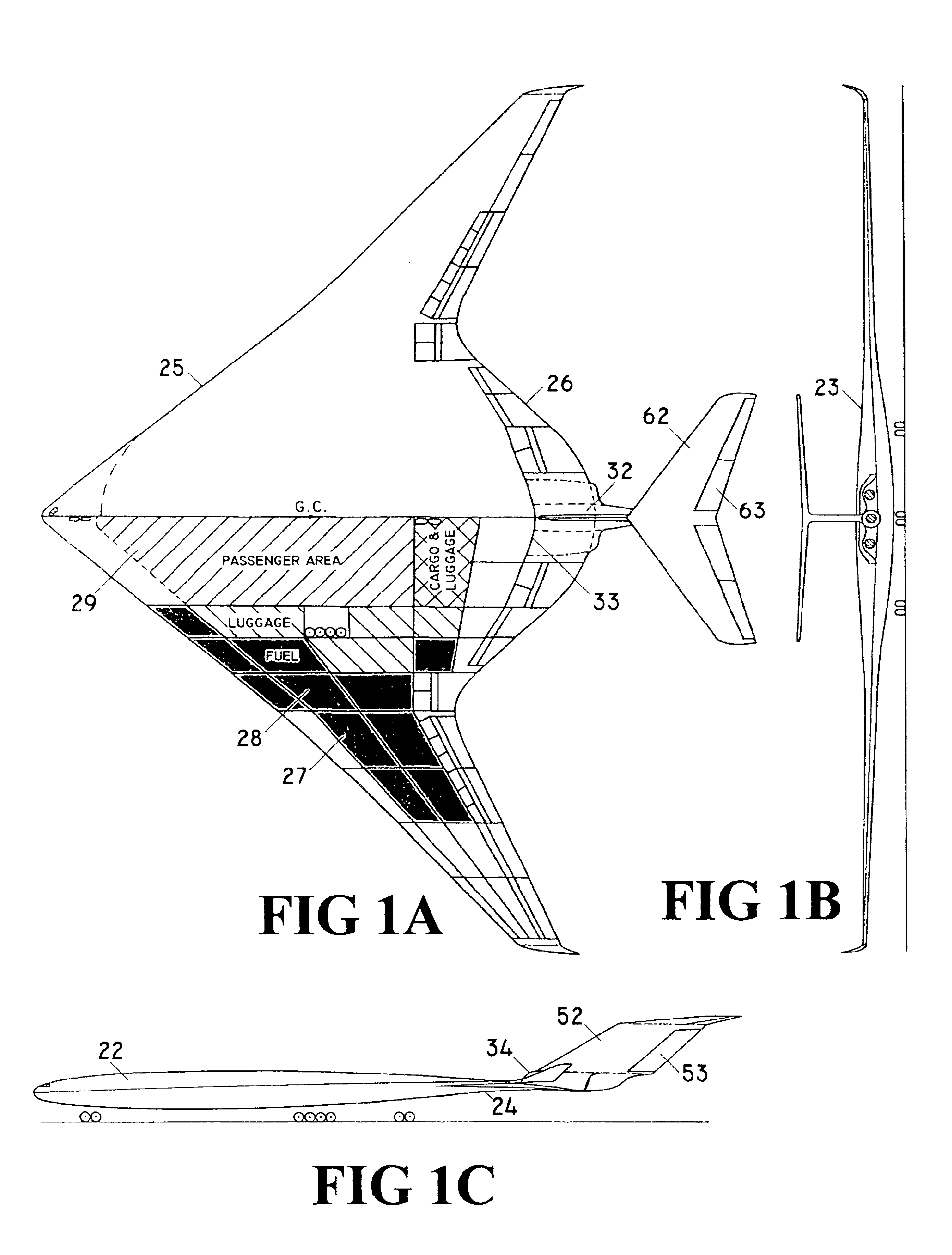
Having this principle as guidance, the project got into serious troubles related to insuring sufficient space for payload accommodation by using relatively thin airfoils, while the wingspan reached proportions that are very close to limiting the maneuver of such aircraft on existing airports.
The problem with shortage of space for payload accommodation was attempted to be resolved by increasing the relative thickness of the airfoils in the payload area, which increased drag and significantly reduced aerodynamic efficiency especially at high subsonic speed.
Another problem is related to insufficient longitudinal stability and maneuver control of the aircraft that is required for civil aircraft, which is the key shortcoming of this concept.
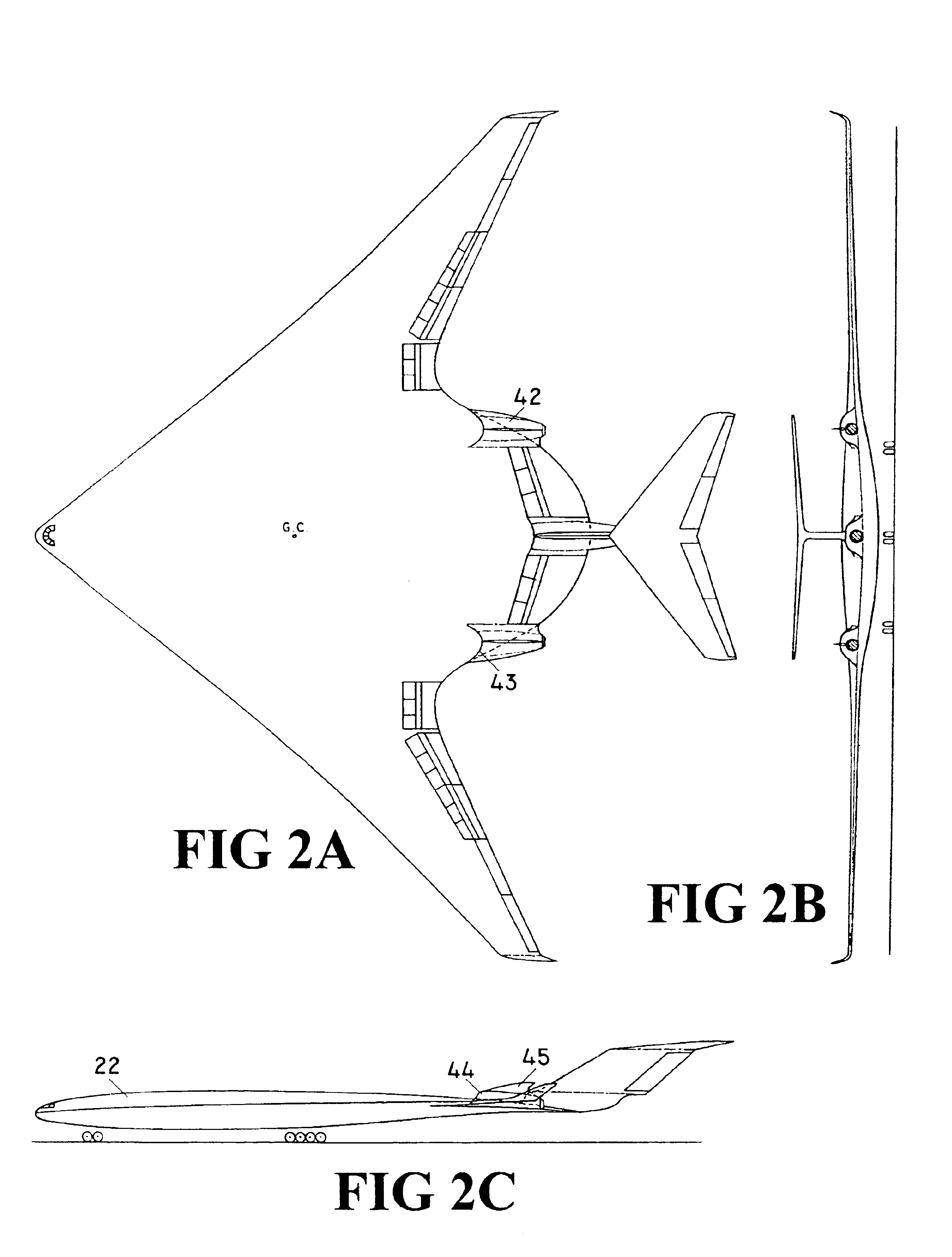
This concept resolved the problem of payload accommodation by using airfoils with relatively low thickness, as well as the problem related to longitudinal stability and maneuver control requirements.
A shortcoming of this concept is unfavorable vertical position of the aft stabilizing aerodynamic surfaces relatively to the external wings that are positioned in front of them.
The stabilizing surfaces are disposed aft of and below external wings, which would significantly reduce their efficiency and thereby flight safety during takeoff and landing when the flaps of the external wings are deflected downwardly.

Method used


Image

  • Tailed flying wing aircraft
  • Tailed flying wing aircraft
  • Tailed flying wing aircraft

Examples


Embodiment Construction

FIGS. 1 to 3 show three aerodynamic concepts of large tailed flying wing subsonic aircraft.

[0065]FIG. 1 shows a new aerodynamic concept for large high subsonic aircraft that is composed from main body 22, central jet engine pylon 32, fin 52 with rudder 53, and tailplane 62 with elevator 63. Main body 22 is shaped as a unique airlifting body that is defined with main body upper surface 23, main body under surface 24, main body leading edge 25, and main body trailing edge 26. Cross sections of main body 22 in airflow direction have airfoil shapes. Merging lines between main body leading edge 25 and main body trailing edge 26 in the direction of airflow represent chords of the main body airfoils.

[0066]Main body 22 along its span has three distinctive sections: main body central section 29, two symmetrical main body transition sections 28, and two symmetrical main body external wings 27. Main body central section 29 with its very long chords represents the largest section of the airlift...


PUM


Abstract

The “Tailed Flying Wing Aircraft” idea represents new aerodynamic concepts for large high subsonic aircraft. Large high subsonic aircraft based on these new aerodynamic concepts are having a significantly higher lift capacity and longer range, as well as a significantly lower fuel consumption of at least two times less than the aircraft based on classical fuselage concept with the same external dimensions. In addition, the aircraft based on the new concepts are having a significantly better longitudinal stability and maneuverability, as well as aerodynamic efficiency at high subsonic speed than aircraft based on “Tailless Flying Wing” concepts. The aircraft based on the “Tailed Flying Wing Aircraft” idea satisfy all safety requirements for civil aircraft. They also have simple shapes for manufacturing, hence this idea provides for new realistic advanced aerodynamic concepts for the next generations of large subsonic aircraft.

Description

BACKGROUND OF THE INVENTION[0001]This invention relates to a new general aerodynamic concept for high-subsonic large civil and military aircraft with a goal to drastically reduce fuel consumption at high subsonic speed and significantly increase lift capacity and range of aircraft relatively to existing classical concept aircraft with simultaneous reduction in external dimensions of aircraft, as well as reduction in runway length in order to utilize existing airport facilities. The new concept simultaneously provides for significantly better stability, maneuverability, and safety relatively to the existing concepts based on the idea of tailless flying wing.[0002]Increase in air traffic volume and very dynamic development thereof have set very challenging goals with respect to moving ever larger payloads safely at large distances as fast as possible at low cost. The former goals have generated very intense research efforts and development of new aerodynamic concepts, materials, and n...

Claims


Application Information

Patent Timeline
Patent Type & Authority Patents(United States)
IPC IPC(8): B64C1/00B64C3/10B64C39/10
CPCB64C1/0009B64C3/10B64C39/10B64D11/00B64C2039/105Y02T50/12Y02T50/46Y02T50/10Y02T50/40
Inventor DIZDAREVIC, FARUKDIZDAREVIC, MITHAD
Owner DIZDAREVIC FARUK
Why Eureka
Try Eureka